BM51_POWER
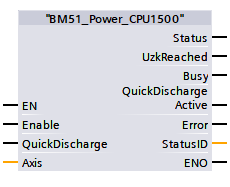
Description
The function module BM51_Power activates the motion control availability of the connected mains inverter (NWR) considering the account the device-side wiring of pulse release and fast discharge resistor.
Attention:
Before calling the drive must have been taken completely into operation
considering all the safety regulations.
|
Parameter Input |
Datatype |
Description |
|
Enable |
BOOL |
Switch on to operational readiness |
|
QuickDischarge |
BOOL |
Activate quick discharge |
|
Parameter Output |
Datatype |
Description |
|
Status |
BOOL |
Status operational readiness |
|
UzkReached |
BOOL |
DC-Link Voltage set value reached |
|
Busy |
BOOL |
Mains inverter switch-on process is busy |
|
QuickDischargeActive |
BOOL |
quick discharge request active |
|
Error |
BOOL |
Error Bit |
|
StatusID |
WORD |
Mains power inverter Status |
|
Parameter In-/Output |
Datatype |
Description |
|
Axis |
UDT |
BM Motion Control axis variable |
Description
The command BM51_Power switches the operational readiness for Motion Control of the Baumüller mains inverters connected to Axis. The BM51_Power command connects the necessary device-side enables such as pulse enable and the software enable to the operational readiness. The operational readiness at the Status output must be switched via the pulse enable and the software enable at the Enable input, whereby the device DC link rapid discharge switch and software input parameter rapid discharge are not switched on.
The following procedure can be used to test the functionality of the operational readiness of the axis variables:
- Create the device DC-Link fast discharge and pulse release on the device side according to the device description.
- Call BM51_Power with BM_ReadAxisError and BM_Reset in a program of the type CYCLIC or OB1.
- Set the Enable input = TRUE and the QuickDischarge input = FALSE. First the output status changes to TRUE, then a few seconds later the output UzkReached changes to TRUE (with 400Vac mains supply voltage on NWR, DC-link voltage actual value changes from 560Vdc(status=TRUE) to 640 Vdc(UzkReached = TRUE)).
- Change the input parameter Enable from TRUE to FALSE and the QuickDischarge input = FALSE, the output UzkReached changes from TRUE to FALSE and the output Status remains TRUE (DC link voltage actual value changed from 640Vdc to 560 Vdc).
- Input parameter Enable = FALSE and QuickDischarge changes from FALSE to TRUE, the output QuickDischargeActive changes from FALSE to TRUE, until the DC-link voltage actual value <20V, outputs QuickDischarge and status change back to FALSE.
- Input parameter Enable = FALSE and QuickDischarge = FALSE.
Behavior in the event of a NWR fault:
For a mains inverter fault or BM_Read / BM_Write error can be reset via BM_Reset, for a mains inverter fault after eliminating the cause of the error, an acknowledgment via BM_Reset (input parameter of BM51_Power must Enable = FALSE). A new start of BM51_Power takes place Enable from FALSE to TRUE change (new start interlock).
Status
control: --
Off Status : --
Recommended calling: OB1
Note:
BM51_Power may only be used together with the BM_Reset, BM_Read, BM_Write and
BM_ReadAxisError, so the connection between device-side enables (pulse enable)
and software-side enable, fast discharge, parameter write, parameter read and
reset errors can be tested comfortably according to Motion Control.
Input Enable:
TRUE: Operational
FALSE: End operational readiness.
Input QuickDischarge
TRUE: Activate quick discharge
FALSE: End quick discharge
Output Status:
TRUE: mains power converter ready for operation.
FALSE: mains power converter not ready for operation.
Output UzkReached:
TRUE: DC-link voltage set value reached
FALSE: DC-link voltage set value not reached.
Output Busy:
TRUE: mains power inverter switch-on process is running
FALSE: mains power inverter switch-on process ended.
Output QuickDischargeActive:
TRUE: mains power inverter DC link voltage quick discharge Process is running.
FALSE: mains power inverter DC link voltage quick discharge process ended.
Output Error:
TRUE: Error active. Info at BM_ReadAxisError.
FALSE: not Error active.
Output StatusID:
Main power inverter status word, parameter number 108.3
Input and Output Axis:
Symbolic BM Motion Control axis variable of the type with UDT.
When programming with the template data block DB5 (symbolic "BM"), the following symbol text should be written: "BM" .AXIS [x] (x is mains power inverter at motion control axis number).