Description
The "BM_FindNotchPosRAFS" function carries out a notch position search (parameter 127.008.0.0) with the "standing wave and variable current feed angle" mode. The axis must not be freely movable during this measuring; after measuring successfully the redetermined notch position is displayed.
The redetermined value already is valid in the RAM controller, a takeover into the controller flash can be made with the BM_DataSetHandling class.
Further
information referring to the notch position search is to be found in the
"Parameter manual of the basic unit bmaXX 5000" chapter 3.9.8
|
Parameter input |
Data type |
Description |
|
Execute |
BOOL |
Edge-sensitive execution |
|
CurrentRise |
REAL |
Current rise [A/s] |
|
CurrentDrop |
REAL |
Current drop [A/s] |
|
TimeConstCurrent |
REAL |
Time constant current [s] |
|
CurrentRef |
REAL |
Current set value notch position search [%] |
|
Angle Rising |
REAL |
Angle rising [U/min] |
|
MaxAngle |
REAL |
Maximum positioning angle [degrees] |
|
ErrLimitMechDeltaAnlge |
REAL |
Error limit mechanical angle change [degrees] |
|
Averaging0SpeedDetect |
REAL |
Averaging zero speed detection |
|
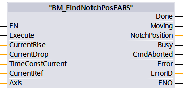
Parameter output |
Data type |
Description |
|
Done |
BOOL |
Notch position search successful. |
|
Moving |
BOOL |
Notch position search is running. |
|
Busy |
BOOL |
Parameter Read/write active. |
|
CommandAborted |
BOOL |
Abort by another motion control command, BM_Stop or error stop |
|
Error |
BOOL |
Parameter Read/write error; Error ID is valid |
|
ErrorID |
DWORD |
Communication error ID Siemens error list |
|
Parameter Input and output |
Data type |
Description |
|
Axis |
UDT |
BM Motion Control Axis Variable |
Description
Before activating the command "BM_FindNotchPosRAFS" BM_Power must be switched off and the axis must be freely movable.
The command �Execute = 1� switches on the Axis notch position search, by an edge-sensitive execution all of the input values are taken over and the command is started at the axis. A new command switching requires a change from FALSE to TRUE at the input �Execute whereby this change can be carried out at the executing time of the command.
Movement command:
The edge-sensitive execution in switched-off BM_Power state. The execution of abort is aborted with BM_Stop, missing operational readiness or Errorstop. In the result message, only one of the output bits Done, Busy, CommandAborted is active
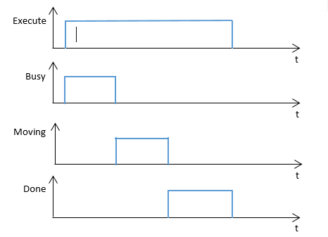
Edge-sensitive execution:
In order to carry out the command the Execute input can be TRUE during one cycle. Then the command is processed. The result is Done = 1 after the successful notch position search, the output parameter Busy, the Command Aborted Error and the Error Id are reset, if the input Execute = 0 (see diagram 1)
Diagram of an edge-sensitive execution:
Diagram 1:
State
control by BM_ReadStatus:
Off state: Standstill.
After state: -
Recommended task: OB1.
Note:
"BM_Power" and other function block must be switched off and the axis must be freely movable.
A command from "BM_FindNotchPosRAFS" must not be activated before a command from another function block has been not successfully executed.
If an error occurs during the command execution, the error must be reset with �BM_Reset�. Function block command will be executed successfully at "BM" .AXIS [x] .DRIVE.BM_AXIS_STATUS.ParmRW_Active = 0.
Input Execute:
TRUE: Edge-sensitive execution, the input parameters and the start notch position search are taken over.
FALSE: No execution or resetting of the FC outputs of Error & Error ID.
Input CurrentRise:
Current rise in the A/s unit.
Minimum: 0.001 [A/s], maximum: 100.0 [A/s]
Default: 1.0 [A/s], if CurrentRise =0.0
Input CurrentDrop:
Current drop in the A/s unit.
Minimum: 0.001 [A/s], maximum: 100.0 [A/s]
Default: 5.0 [A/s], if CurrentDrop =0.0
Input TimeConstCurrent:
The parameter sets the time which is at least required of the constant current phase during notch position search.
Minimum: 0.01 [s] = 0.0[s], maximum: 10.0 [s]
Default: 1.0 [s], if TimeConstCurrent =0.0
Input CurrentRef:
Current of the notch position search. Standardization: 100% comply with the motor nominal current.
Minimum: 0.01 [%] = 0.0[%], maximum: 100.0 [%]
Default: 50.0 [%], if parameter CurrentRef=0.0
Input AngleRising:
The parameter specifies the change of the angle, where the electrical angle is corrected during the notch position search with "standing wave and a more variable current feed angle".
Minimum: 1.0 [U/min], maximum: 59999.0 [U/min]
Default: 1.0 [U/min], if parameter AngleRising =0.0
Input MaxAngle:
Setting of the window for permitted mechanical motion during notch position search with "standing wave and a more variable current feed angle", before the correction of the electrical angle is carried out.
Minimum: 0.05 [degrees], maximum: 360.00 [degrees]
Default: 8.00 [degrees], if the parameter MaxAngle =0.0
Input ErrLimitMechDeltaAngle:
Setting of the window for permitted mechanical motion during notch position search with "standing wave and more variable current feed angle" before an error is released.
Minimum: 0.05 [degrees], maximum: 360.00 [degrees]
Default: 0.50 [degrees], if the parameter MaxAngle =0.0
Input Averaging0SpeedDetect:
This parameter is used to detect 0 speed during notch position search with "standing wave and more variable current feed angle". The higher the width the lower the measured motion of the motor may be.
Requirement for 0 speed: Averaging0SpeedDetect x_Delta_Phi /ms < MaxAngle.
Minimum: 1.0, maximum: 1024.0
Default: 100.0, if parameter Averaging0SpeedDetect =0.0
Output Done:
TRUE: Notch position search is executed. Drive state changes from Enable operation to Ready-to-switch-on.
FALSE: Not activated.
Output Moving:
TRUE: Notch position search is running.
FALSE: not activated.
Output Busy:
TRUE: The service communication of the parameter Read/write actvie or Target position not reached, yet during an initiated positioning.
FALSE: Not activated.
Output CommandAborted:
TRUE: Abort due to another motion control command, BM_Stop command, error stop or a missing operating availability to BM_Power.
FALSE: Not activated.
Output Error:
TRUE: An error at the service communication of the parameter Read/write is available. Information to error ID is valid and error information, refer to S7 in the manual.
FALSE: No error activated.
Output ErrorID:
The information of service communication error (detailed information refer to S7 in the manual)
Input and output Axis:
Symbolic BM Motion Control axis variable of an UDT type.
While programming the data module template DDB5 (symbolic �BM�) it is to be written with the following symbol text: "BM".AXIS[x] (x is drive axis number).