BM_Home
Description
The Motion Control FC BM_Home references the drive axis using the method set at the drive. The setting of the method at the drive can be made via Prodrive and/or in the program using the BM_HomeInit, BM_HomeInitBlock Baumueller addition-FCs.
Note:
The indicated origin position must be within the travelling distance (software
limit switch 1/2).
|
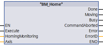
Parameter Input |
Data Type |
Description |
|
Execute |
BOOL |
Edge-sensitive execution of homing |
|
HomingMonitoring |
Timer |
Timer T for Homing time monitoring |
|
Parameter Ouput |
Data Type |
Description |
|
Done |
BOOL |
Homing is executed. The axis changes into the standstill state |
|
Moving |
BOOL |
Homing started and target not reached. |
|
Busy |
BOOL |
Parameter Read/Write active. |
|
CommandAborted |
BOOL |
Abort by time monitoring, BM_Stop or Errorstop |
|
Error |
BOOL |
Parameter Read/Write error; ErrorID is valid |
|
ErrorID |
DWORD |
Communication ErrorID-Siemens error list |
|
Parameter Input and Output |
Data Type |
Description |
|
Axis |
UDT |
BM Motion Control axis variable |
Description
The command BM_Home references the drive by an absolute position from the Standstill state and changes into the Homing state. The indicated position must be within the travelling range (software limmit switch 1/ software limit switch 2). The FC BM_Home can be aborted by BM_Stop. The homing functionality can be monitored by an application monitoring time (Application Timeout) during the execution refer to FCs BM_HomeInit...). This monitoring especially is appropriate during long travelling distances with home switches (HomeSwitch). If the application monitoring time is zero then this functionality is deactivated.
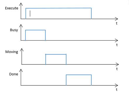
Edge-sensitive execution:
In order to carry out the command the Execute input can be TRUE during one cycle. Then the command is processed. The result is Done = 1 after the successful notch position search, the output parameter Busy, the Command Aborted Error and the Error Id are reset, if the input Execute = 0 (see diagram 1)
Diagram for the edge-sensitive execution:
Diagram 1:
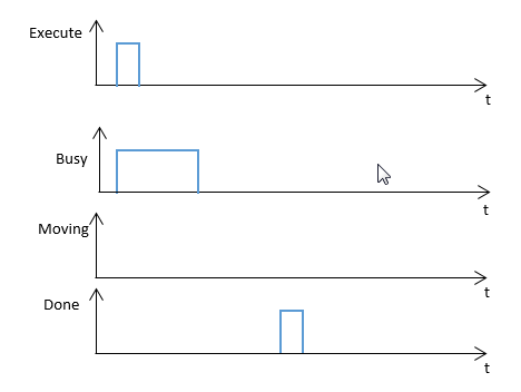
Diagram 2:
Status
control via BM_ReadStatus
From status: Standstill.
To status: Homing.
Note:
The stopping on a defined position is not possible therefore after calling up
BM_Stop the drive must be referenced with BM_Home again.
A command from "BM_Home" must not be activated before a command from another function block has been not successfully executed.
If an error occurs during the command execution, the error must be reset with "BM_Reset". Function block command will be executed successfully
at "BM" .AXIS [x] .DRIVE.BM_AXIS_STATUS.ParmRW_Active = 0.
Input Execute:
TRUE:
Edge-sensitive execution of homing
FALSE: No execution or reset of the FC-outputs if Done is TRUE already.
Attention: Homing start at BM_ReadStatus parameter parameter Standstill = 1, only.
Input HomingMonitoring:
Timer T for homing time monitoring.
Output Done:
TRUE:
Homing is executed. Drive changes from Homing status to standstill.
FALSE: Homing is active or not possible.
Output Moving:
TRUE: homing position not reached yet at Homing start.
FALSE: not activated.
Output Busy:
TRUE: The service communication for the parameter Read/Write active or
FALSE: Not activated.
Output CommandAborted:
TRUE:
Abort by BM_Stop; Errorstop or missing availability at BM_Power.
FALSE: Not active.
Output Error:
TRUE: There is an error at Service communication for the Read/Write parameter
For information on the valid ErrorID and Error information refer to S7 Description.
FALSE: No active error.
Output ErrorID:
The information of service communication error (for detailed information refer to S7 Description)
Notes:
Time monitoring abort: Error = 1 and ErrorID = 0
Output ErrorID:
The output of service communication errors (detailed information refer to S7 Description).
Input and output Axis
UDT type symbolic BM Motion Control axis variable.
During the programming with the template data module DB5 (symbolic "BM") the following symbol text must be used: "BM".AXIS[x] (x is the drive axis number).