BM_HomeInit
Description
The Motion Control command BM_HomeInit is an extension of the Motion Control standard and initializes the homing method "Homing in the travelling distance" for the Motion Control command BM_Home.
|
Parameter Input |
Data Type |
Description |
|
Execute |
BOOL |
Edge-sensitive execution |
|
Method |
INT |
Homing method |
|
Position |
REAL |
Homing position |
|
Velocity |
REAL |
Target speed absolute value of homing |
|
EndVelocity |
REAL |
Final target speed absolute value of homing, [Inc/ms] |
|
Acc |
REAL |
Homing acceleration absolute value, [Inc/ms²] |
|
Dec |
REAL |
Deceleration absolute value of homing; [Inc/ms²] |
|
Jerk |
REAL |
Jerk absolute value; [Inc/ms³] |
|
TimeoutHoming |
S5Time |
Monitoring time of the execution |
|
Parameter Output |
Data Type |
Description |
|
Initialised |
BOOL |
Homing method installed successfully |
|
Busy |
BOOL |
Parameter Read/Write active |
|
Error |
BOOL |
Parameter Read/Write error; ErrorID is valid |
|
ErrorID |
DWORD |
Communication ErrorID-Siemens error list |
|
Parameter Input and output |
Data Type |
Description |
|
Axis |
UDT |
BM Motion Control axis variable |
The homing mode with the input method is set at the drive. Then homing can be started by the BM_Home command and the drive can be referred to with the accordant homing method.
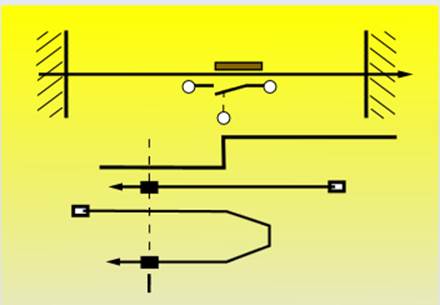
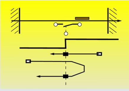
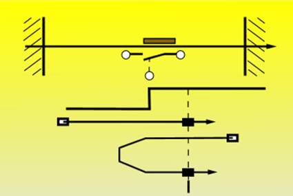
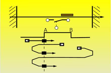
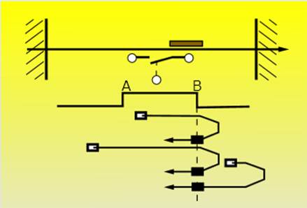
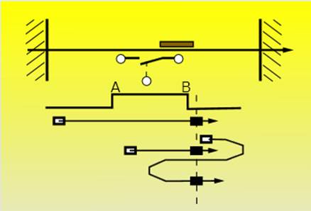
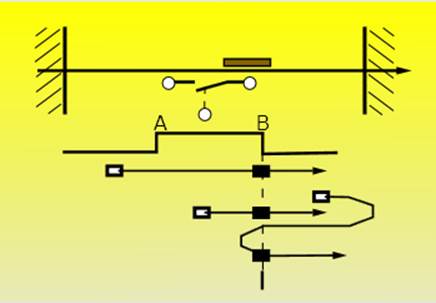
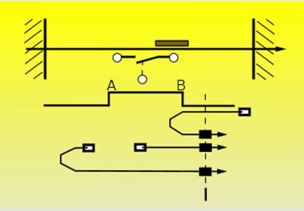
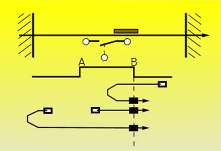
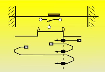
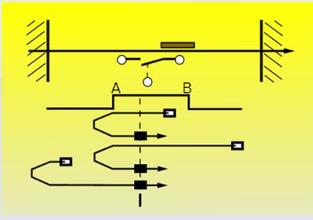
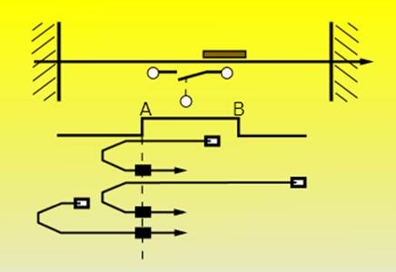
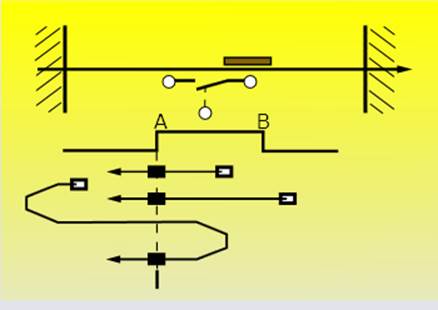
Homing Method – Setting of the Homing Mode
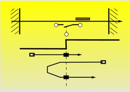
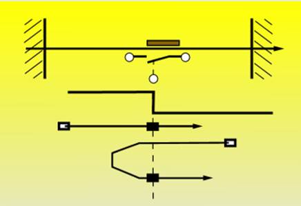
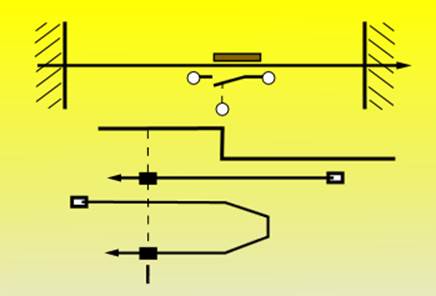
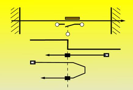
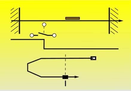
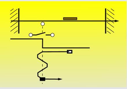
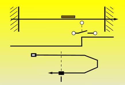
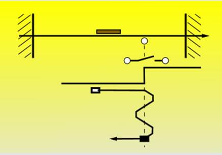
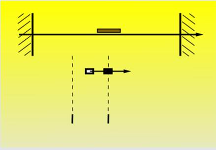
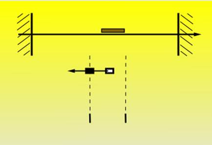
Homing with HomeSwitch
Method = 3 (positive switch with zero pulse, counterclockwise rotation)
Method = 19 (positive switch without zero pulse, counterclockwise rotation)
Method = 4 (positive switch with zero pulse, clockwise rotation)
Method= 20 (positive switch without zero pulse, clockwise rotation)
Method = 5 (negative switch with zero pulse, clockwise rotation)
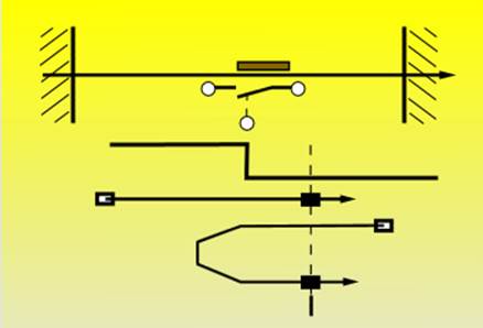
Method = 21 (negative switch without zero pulse, clockwise rotation)
Method = 6 (negative switch with zero pulse, counterclockwise rotation)
Method = 22 (negative switch without zero pulse, counterclockwise rotation)
Method = 7 (switch to the left of edge A, with zero pulse, clockwise rotation)
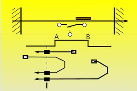
Method = 23 (switch to the left of edge A, without zero pulse, clockwise rotation)
Method = 8 (switch to the right of edge A, with zero pulse, clockwise rotation)
Method = 24 (switch to the right of edge A, without zero pulse, clockwise rotation)
Method = 9 (switch to the left of edge B, with zero pulse clockwise rotation)
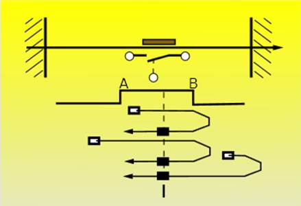
Method = 25 (switch to the left of edge B, without zero pulse, clockwise rotation)
Method = 10 (switch to the right of edge B, with zero pulse, clockwise rotation)
Method = 26 (switch to the right of edge B, without zero pulse, clockwise rotation)
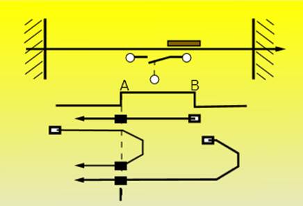
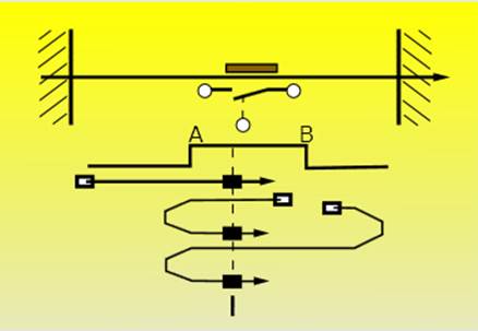
Method = 11 (switch to the right of edge B, with zero pulse, counterclockwise rotation)
Method = 27 (switch to the right of edge B, without zero pulse counterclockwise rotation)
Method = 12 (switch to the left of edge B, with zero pulse, counterclockwise rotation)
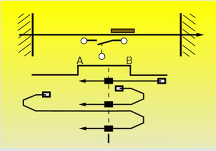
Method = 28 (switch to the left of edge B, without zero pulse, counterclockwise rotation)
Method = 13 (switch to the right of edge A, with zero pulse, counterclockwise rotation)
Method = 29 (switch to the right of edge A, without zero pulse, counterclockwise rotation)
Method = 14 (switch to the left of edge A, with zero pulse, counterclockwise rotation)
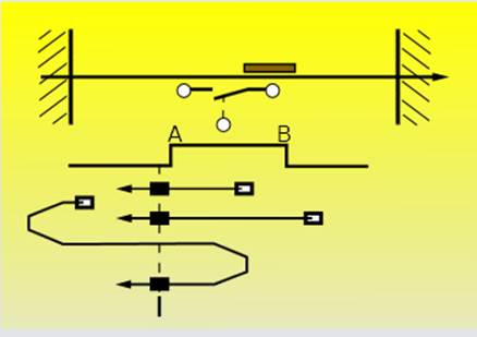
Method = 30 (switch to the left of edge A, without zero pulse, counterclockwise rotation)
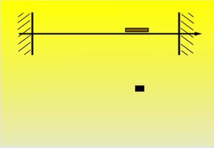
Homing with LimitSwitch
Method = 1 (negative limit switch with zero pulse)
Method = 17 (negative limit switch without zero pulse)
Method = 2 (positive limit switch with zero pulse)
Method = 18 (positive limit switch without zero pulse)
Homing with zero pulses
Method = -1 or 34 (approaching the encoder zero angle clockwise rotation)
Method = -2 or 33 (approaching the encoder zero angle, counterclockwise rotation)
Homing including the setting of the home position
Method = -3 or 35 (approaching the encoder zero angle, counterclockwise rotation)
In the user program the setting by referring to the drive can be changed in the Standstill, DiscreteMotion, ContinuousMotion, SynchronizedMotion states accordant to the running time.
Edge-sensitive execution:
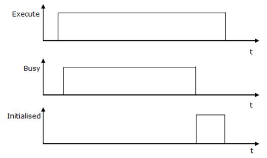
To carry out the command the input Execute must be TRUE for one cycle only (see diagramm 1). Then the command is carried out, the result Initialized signals for a period of one cycle only if the input Execute = 1. Then the command is executed, the result Initialized = 1. Initialized is reset if the input Execute = 0. (See diagramm 2)
Diagram for edge-sensitive execution:
Diagram 1:
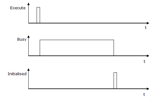
Diagram 2:
Status control via BM_ReadStatus:
From status: Standstill, DiscreteMotion, ContinuousMotion,
SynchronizedMotion.
Recommended task: OB1.
Note:
The FC BM_HomeInit overwrites drive parameterizations that were set via the service communication sources, such as Prodrive.
Required digital I/Os: positive and negative switch parameterizes and links in Prodrive.
If the method is set to zero then the homing method is set to the unit sided "Set home position" (35 or -3) at the drive.
A command from "BM_HomeInit" must not be activated before a command from another function block has been not successfully executed.
If an error occurs during the command execution, the error must be reset with "BM_Reset". Function block command will be executed successfully at
"BM" .AXIS [x] .DRIVE.BM_AXIS_STATUS.ParmRW_Active = 0.
Input Execute:
TRUE:
Edge-sensitive execution, the input parameters are accepted.
FALSE: No execution or reset of the FC outputs if Initialized is TRUE at the
time of Execute
= FALSE
Input Method:
Homing method of the drive
Input Position:
Home position, specification as an absolute value in increments
Input Velocity:
Specification in increments per milliseconds. This is the maximum target speed of the drive movement.
Input EndVelocity:
Specification in increments per milliseconds. This is the maximum final target speed of the drive movement.
Input Acc:
Positive acceleration in increments per milliseconds2
Minimum: 0.07 [Inc/ms²], maximum: 655.35 [Inc/ms²]
Default: 2.00 [Inc/ms²]
Input Dec:
Negative acceleration in increments per milliseconds.
Minimum: 0.07 [Inc/ms²], maximum: 655.35 [Inc/ms²]
Default: 2.00 [Inc/ms²]
Input Jerk:
Acceleration positioning jerk in increments per milliseconds3 .
Minimum: 0.07 [Inc/ms³], maximum: 655.35 [Inc/ms³]
Default: 0.25 [Inc/ms³]
Input TimeoutHoming:
Specification
of the monitoring time with S5Time.
0: Activation of monitoring at calling up BM_Home deactivated.
>0: Monitoring accordant the Homing specification active.
Output Initialised:
TRUE
: Homing methods installed successfully.
FALSE : Not possible.
Output Busy:
TRUE: The service communication for the parameter
Read/Write is active.
FALSE: Not active.
Output Error:
TRUE: An error at the service communication for the parameter Read/Write is available. Refer to S7 Description for information on valid ErrorID and Error information
FALSE: No error active.
Output ErrorID:
The information of service communication error (for detailed information refer to S7 Description)
Input and output Axis:
UDT type symbolic BM Motion Control axis variable.
During the programming with the template data module DB5 (symbolic "BM") the following symbol text must be used: "BM".AXIS[x] (x is the drive axis number).