Description
The Motion Control command BM_MoveAbsolute carries out a controlled movement to the specified position.
|
Parameter Input |
Data Type |
Description |
|
Execute |
BOOL |
Edge-sensitive execution |
|
Position |
REAL |
Absolute target position; [Inc] |
|
Velocity |
REAL |
Absolute value of the target positioning speed; [Inc/ms] |
|
Acceleration |
REAL |
Absolute value of the acceleration within the target positioning; [Inc/ms²] |
|
Deceleration |
REAL |
Absolute value of the deceleration within the target positioning; [Inc/ms²] |
|
Jerk |
REAL |
Jerk Absolute value; Default [Inc/ms³] |
|
Direction |
BOOL |
Positioning direction; 0: Shortest way |
Parameter Output |
Data Type |
Description |
|
Done |
BOOL |
Target position reached. The axis changes in the Standstill state |
|
Moving |
BOOL |
Positioning started and target not reached. |
|
Busy |
BOOL |
Parameter Read/Write active |
|
CommandAborted |
BOOL |
Abort by another Motion Control command, BM_Stop or Errorstop |
|
Error |
BOOL |
Parameter Read/Write error; ErrorID is valid |
|
ErrorID |
DWORD |
Communication ErrorID-Siemens error list |
|
Parameter Input and output |
Data Type |
Description |
|
Axis |
UDT |
BM Motion Control axis variable |
Description
The command BM_MoveAbsolute carries out a controlled absolute positioning. The command switches the axis in the DiscreteMotion state of BM_ReadStatus and completes with Done = TRUE and the standstill state. An edge-sensitive execution is carried out by Execute = TRUE whereby the input values are accepted and the command is implemented at the drive defined at Axis. A new entering of the command requires a FALSE to TRUE change at the input Execute whereby this change can be carried out during the execution time of the command.
Movement command:
The edge-sensitive execution causes an abort of the active movement command. The execution of the abort is executed by BM_Stop, missing availability at the BM_Power or Errorstop. The result message has only one valid output bit (Done Busy, CommandAborted)
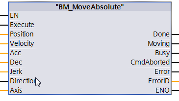
Edge-sensitive execution:
To execute the command the input Execute can be one cycle TRUE (see diagram 1). Then the command is executed, the result Done is displayed for one cycle if the input Execute =1. Then the command is executed, the result Done = 1. Done = 1 is reset if the input execute = 0 (see diagram 2).
Diagram for the edge-sensitive execution:
Diagram 1:
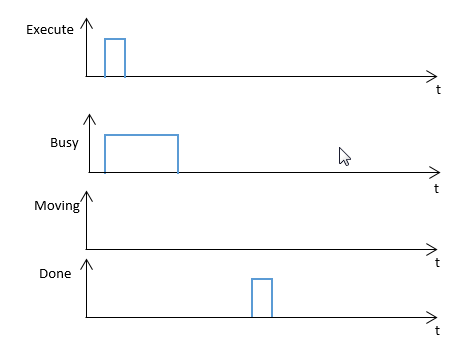
Diagram 2:
Status
control via BM_ReadStatus
From status: Standstill, DiscreteMotion, ContinuousMotion, SynchronizedMotion.
To status: DiscreteMotion.
Recommended task: OB1.
Note:
The specified target position must be within the positioning distance and can be limited by unit-sided as well as software limit switches. If the DiscreteMotion state is left into another movement state then Homing (BM_Home) must be executed if required.
A command from "BM_MoveAbsolute” must not be activated before a command from another function block has been not successfully executed.
If an error occurs during the command execution, the error must be reset with “BM_Reset”. Function block command will be executed successfully at
"BM" .AXIS [x] .DRIVE.BM_AXIS_STATUS.ParmRW_Active = 0.
Input Execute:
TRUE
= Edge-sensitive execution, the input parameter are accepted.
FALSE = No execution or reset of the FC outputs if Initialized is TRUE at the
time of Execute = FALSE.
Input Position:
Specification in increments. The axis rotation of a Baumüller drive complies with a resolution of 65536 increments that also are called user units.
Input Velocity:
Specification in increments per milliseconds. This is the maximum speed of the target positioning which does not have to be reached necessarily.
Input Acceleration:
Positive acceleration in increments per milliseconds2
Minimum: 0.07 [Inc/ms²], maximum: 655.35 [Inc/ms²]
Default: 2.00 [Inc/ms²]
Input Deceleration:
Negative acceleration in increments per milliseconds.
Minimal: 0.07 [Inc/ms²], maximal: 655.35 [Inc/ms²]
Default: 2.00 [inc/ms²]
Input Jerk:
Acceleration positioning jerk in increments per milliseconds³.
Minimum: 0.07 [Inc/ms³], maximum: 655.35 [Inc/ms³]
Default: 0.25 [Inc/ms³]
Input Direction:
Specification of the positioning direction.
FALSE:
Shortest way
TRUE: Longest way
Output Done:
TRUE
= Positioning was executed. Axis changes into the Standstill status.
FALSE = Not active.
Output Moving:
TRUE:
the target position was not reached during a initiated
positioning.
FALSE: not active.
Output Busy:
TRUE: The service communication of the Read/Write parameter is active.
FALSE: Not active.
Output CommandAborted:
TRUE:
Abort by another Motion Control command, BM_Stop command, Errorstop or missing
availability at the BM_Power.
FALSE: Not active.
Output Error:
TRUE: There is an error at Service communication for the Read/Write parameter. For information on the valid ErrorID and Error information refer to S7 Description
FALSE: No active error.
Output ErrorID:
The information of service communication error (for detailed information refer to S7 Description)
Input and output Axis:
UDT type symbolic BM Motion Control axis variable.
During the programming with the template data module DB5 (symbolic “BM”) the following symbol text must be used: "BM".AXIS[x] (x is the drive axis number).