BM_Power_EA_CPU1500
Description
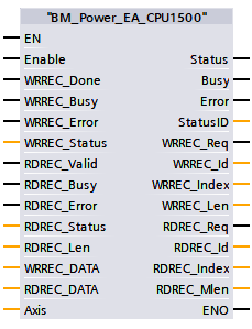
The FC BM_Power_EA_CPU1500 switches the operational readiness of the connected Baumüller single-axis drive with BM_Power_Com_CPU1500, taking into account the device-side wiring of pulse enable and quick stop.
Attention:
Before the call, the drive must be fully commissioned, taking into account all safety regulations.
With "BM".AXIS[x].DRIVE.POWER.NoSetHomingMode := TRUE, the operating mode of homing can be deactivated when calling up Power On.
|
Parameter Input |
Data Type |
Description |
|
Enable |
BOOL |
Switch to operational readiness |
|
NoCmd_Axis |
CPU1500_BM_AXIS_REF |
BM Motion Control Axis Reference |
|
WRREC_Done |
BOOL |
Done=1: Parameter write was successfully transferred |
|
WRREC_Busy |
BOOL |
Busy=1: Parameter write process is not yet not yet finished |
|
WRREC_Error |
BOOL |
Error=1: An error occurred during the parameter write process |
|
WRREC_Status |
DWORD |
WRREC Module status or error information |
|
RDREC_Valid |
BOOL |
Valid=1: Read parameter was successfully received |
|
RDREC_Busy |
BOOL |
Busy=1: Parameter Read operation is not yet completed |
|
RDREC_Error |
BOOL |
Error=1: An error occurred during the Parameter read operation |
|
RDREC_Status |
DWORD |
RDREC Module status or error information |
|
RDREC_Len |
UINT |
Data length of the read parameters |
|
Parameter Output |
Data Type |
Description |
|
Status |
BOOL |
Status of operational readiness |
|
Busy |
BOOL |
Drive switch-on process running |
|
Error |
BOOL |
Error bit |
|
StatusID |
WORD |
Drive status |
|
WRREC_Req |
BOOL |
Perform parameter write |
|
WRREC_Id |
HW_IO |
Identification number of the Hardware component |
|
WRREC_Index |
DINT |
Parameter Write Index |
|
WRREC_Len |
UINT |
Parameter Write length in byte |
|
RDREC_Req |
BOOL |
Perform parameter read |
|
RDREC_Id |
HW_IO |
Identification number of the Hardware component |
|
RDREC_Index |
DINT |
Parameter Read Index |
|
RDREC_Mlen |
UINT |
Max. Length of the parameter information to be read in bytes |
|
Parameter Input and Output |
Data Type |
Description |
|
WRREC_DATA |
Struct |
WRREC Data structure |
|
RDREC_DATA |
Struct |
REREC Data structure |
|
Axis |
CPU1500_BM_AXIS_REF |
BM Motion Control Achse Referenz Daten |
Description
The command BM_Power_EA_CPU1500 switches the operational readiness for motion control of the Baumüller double axis device specified on the axis. The command connects the necessary device-side releases such as quick stop and pulse release and the software release (enable) to the operational readiness. The operational readiness at the Status output must be switched via the pulse enable and the software enable at the Enable input, whereby the quick-stop safety switch is not active. To test the functionality of the operational readiness of the axis variables, proceed as follows:
- Quick stop and pulse enable on the unit side according to the unit description.
- Call BM_Power with BM_ReadStatus, BM_ReadAxisStatus and BM_Reset in a programme of type CYCLIC or OB1.
- Set input Enable = TRUE. The output Status must change to TRUE.
- Switch off quick stop. The Status output must change to FALSE whereby the StatusID output reports drive status bits.
- Switch on quick stop. After input Enable, change from FALSE to TRUE. The drive is again at standstill with BM_Power output status = TRUE.
Behaviour in the case of a drive disorder:
- In the event of a drive fault (ErrorStop), an acknowledgement can be carried out via BM_Reset after the cause of the fault has been rectified. After leaving the ErrorStop state via BM_Reset, a restart (status = TRUE) must be carried out via a FALSE after TRUE change at the Enable input (restart interlock).
Necessary:
Library from BM_PROFINET_TIA_14_bd10, BM_Power_COM_CPU1500, Siemens Decentralised Periphery, RDREC(data set read), WRREC(data set write) and addressing of data Module BM
Status control via BM_ReadStatus:
Off Status: Standstill (BM_ReadStatus).
Call Recommended: OB1
Notes:
The command should not be activated if "BM".AXIS[x].DRIVE.BM_AXIS_STATUS.ParmRW_Active =1, Error through BM_Reset reset.
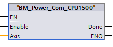
If the command BM_Power_EA_CPU1500 is used together with BM_Power_COM_CPU1500, BM_ReadStatus, BM_ReadAxisStatus, BM_ReadAxisError and BM_Reset, it is possible to conveniently test the connection between device-side enable (quick stop, pulse enable) and the software enable according to Motion Control.
In order to be able to read and write acyclic controller parameters, the decentralised peripheral system components SFB52(RDREC) and SFB53(WRREC) must be used.
The system function block can be found in the Extended instructions under decentral periphery at Siemens Tia Portal program.
Input Parameter Enable
TRUE: Ready for operation.
FALSE: End operational readiness.
Input Parameter NoCmd_Axis
This parameter input represents the number of an axis of double axis device that has not been controlled by this power module.
Input Parameter WRREC_Done:
The parameter input is connected to the output parameter DONE of the Siemens decentralised periphery WRREC.
Input Parameter WRREC_Busy:
The parameter input is connected to the output parameter BUSY of the Siemens decentralised periphery WRREC.
Input Parameter WRREC_Error:
The parameter input is connected to the output parameter ERROR of the Siemens decentralised periphery WRREC.
Input Parameter WRREC_Status:
The parameter input is connected to the output parameter STATUS of the Siemens decentralised periphery WRREC.
Input Parameter RDREC_Valid:
The parameter input is connected to the output parameter VALID of the Siemens decentralised periphery RDREC.
Input Parameter RDREC_Busy:
The parameter input is connected to the output parameter BUSY of the Siemens decentralised periphery RDREC.
Input Parameter RDREC_Error:
The parameter input is connected to the output parameter ERROR of the Siemens decentralised periphery RDREC.
Input Parameter RDREC_Status:
The parameter input is connected to the output parameter STATUS of the Siemens decentralised periphery RDREC.
Input Parameter RDREC_Len:
The parameter input is connected to the output parameter LEN of the Siemens decentralised periphery RDREC.
Output Parameter Status:
TRUE : Drive ready for operation.
FALSE : Drive not ready for operation.
Output Parameter Busy:
TRUE: The drive switch-on process is running.
FALSE: Drive switch-on process completed.
Output Parameter Error:
TRUE: Error active. Info to BM_ReadAxisError valid.
FALSE: No error active.
Output Parameter StatusID:
bmaXX Status Word, Parameter Number 108.3
Output Parameter WRREC_Req:
Der Parameter Ausgang bindet mit Eingang Parameter REQ von Siemens Dezentrale Peripherie WRREC ein.
Ausgang Parameter WRREC_Id:
The parameter output is connected to the input parameter ID of the Siemens decentralised periphery WRREC.
Output Parameter WRREC_Index:
The parameter output is connected to the input parameter INDEX of the Siemens decentralised periphery WRREC.
Output Parameter WRREC_Len:
The parameter output is connected to the input parameter LEN of the Siemens decentralised periphery WRREC.
Output Parameter RDREC_Req:
The parameter output is connected to the input parameter REQ of the Siemens decentralised periphery RDREC.
Output Parameter RDREC_Id:
The parameter output is connected to the input parameter ID of the Siemens decentralised periphery RDREC.
Output Parameter RDREC_Index:
The parameter output is connected to the input parameter INDEX of the Siemens decentralised periphery RDREC.
Output Parameter RDREC_Mlen:
The parameter output is connected to the input parameter MLEN of the Siemens decentralised periphery RDREC.
Input and Outputparameter WRREC_DATA:
Input/Output Parameters WRREC_DATA contains the specific parameter data of the Baumüller Profinet device that is to be written
For more information see manual bmaXX Profinet IRT Device for bmaXX 2500/3300/5000
|
WRREC_DATA |
STRUCT |
Description |
|
ParaId_F |
BYTE |
0: with scalar parameters, 1: with structures or arrays |
|
ParaId_DS |
BYTE |
0: current data set, 1-7: Data set 1-7 |
|
ParaId_FBT |
INT |
Function block type |
|
ParaId_FBI |
BYTE |
Instance/index of the function block |
|
ParaId_PNR |
BYTE |
Parameter number |
|
Index0 |
INT |
Index level-0 |
|
Index1 |
INT |
Index level-1 |
|
Index2 |
INT |
Index level-2 |
|
Index3 |
INT |
Index level-3 |
|
Axis |
BYTE |
0: Axis 1, 1: Axis 2 |
|
Data Type |
BYTE |
Data length value |
|
Data_DW |
DWORD |
Parameter data to be written |
Input and Outputparameter RDREC_DATA:
Input/Output Parameters RDREC_DATA contains the specific parameter data of the Baumüller Profinet device that is to be written
For more information see manual bmaXX Profinet IRT Device for bmaXX 2500/3300/5000
|
RDREC_DATA |
STRUCT |
Description |
|
ParaId_F |
BYTE |
0: with scalar parameters, 1: with structures or arrays |
|
ParaId_DS |
BYTE |
0: current data set, 1-7: data set 1-7 |
|
ParaId_FBT |
INT |
Function block type |
|
ParaId_FBI |
BYTE |
Instance/index of the function block |
|
ParaId_PNR |
BYTE |
Parameter number |
|
Index0 |
INT |
Index level-0 |
|
Index1 |
INT |
Index level-1 |
|
Index2 |
INT |
Index level-2 |
|
Index3 |
INT |
Index level-3 |
|
Axis |
BYTE |
0: Axis 1, 1: Axis 2 |
|
Data type |
BYTE |
Data length value |
|
RC |
DWORD |
Return-Code |
|
Data |
DWORD |
Parameter data to be read |
Ein-/Ausgang Parameter Axis:
Input/output parameter Axis is the number of the controlled bmaXX drive unit.
The BM Motion Control reference of type CPU1500_BM_AXIS_REF Axis, the BM Motion Control reference of type CPU1500_BM_AXIS_REF is connected. When programming with the data block template "DB5" the variable is used as follows the variable is used as follows: BM.AXIS[x]
Where "x" is the axis number of the drive.