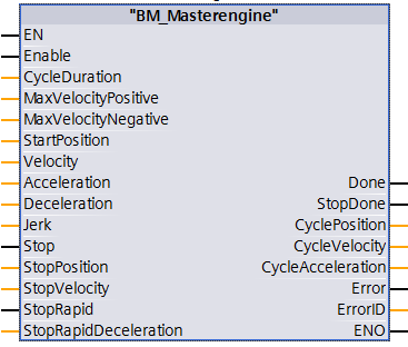
Description
This functional module for Motion Control IRT OB61 is used to generate set values of a virtual master axis. The functional module converts one position in each call-up cycle (OB61-task) according to the specifications of velocity and acceleration.
Note:
The FB BM_Master Engine output variable can be used as input variable of
BM_SyncIn, it must be considered that BM_SyncIn is 32 bit angle value and the
output variable of BM_Master Engine has a value of 9 – 31 bit.
|
Parameter Input |
Data Type |
Description |
|
Enable |
BOOL |
Start master axis |
|
CycleDuration |
USINT |
Resolution of the master axis, convert to BYTE at CPU300 |
|
MaxVelocityPositive |
UDINT |
Maximum positive velocity convert to DWORD at CPU300 |
|
MaxVelocityNegative |
UDINT |
Maximum negative velocity (amount), convert to DWORD at CPU300 |
|
StartPosition |
UDINT |
Start position, convert to DWORD at CPU300 |
|
Velocity |
DINT |
Set velocity, direction by signs |
|
Acceleration |
UDINT |
Amount of acceleration, convert to DWORD at CPU300 |
|
Deceleration |
UDINT |
Amount of deceleration, convert to DWORD at CPU300 |
|
Jerk |
UDINT |
Jerk, convert to DWORD at CPU300 |
|
Stop |
BOOL |
Stop command, stop master axis to stop position |
|
StopPosition |
UDINT |
StopPosition of Stop command, convert to DWORD |
|
StopVelocity |
UDINT |
Amount of StopVelocity of the Stop command, convert to DWORD at CPU300 |
|
StopRapid |
BOOL |
StopRapid command, stop maximum master axis with StopRapidDeceleration without observing the stop position |
|
StopRapidDeceleration |
UDINT |
Amount of StopRapidDeceleration of the StopRapid, convert to DWORD at CPU300 |
Parameter Output |
Data Type |
Description |
|
Done |
BOOL |
Master axis is active |
|
StopDone |
BOOL |
Master axis is stopped with the command Stop or StopRapid |
|
CyclePosition |
UDINT |
Master axis position, The DWORD is at CPU300 |
|
CycleVelocity |
DINT |
Acceleration of the master axis |
|
CycleAcceleration |
DINT |
Acceleration of the master axis |
|
Error |
BOOL |
Error bit, error information ErrorID is valid |
|
ErrorID |
WORD |
ErrorID error list |
The FB BM_MasterEngine converts a master axis position of the virtual master axis during every cyclic call-up. The BM_MasterEngine output parameter CyclePosition can integrate input parameters with BM_SyncIn, but the resolution of CyclePosition must be converted to the input value of BM_SyncIn, the input value of BM_SyncIn is the 32bit angle value and the CyclePosition is the 9-31bit angle value.
In the first cycle immediately the calculation of the master axis position is started by Enable = TRUE. The output Done = TRUE confirms the active cyclic calculation. The output Done = TRUE is to be used with Velocity = Zero to activate (input execute) the function modules BM_SyncIn.
Dependent of the inputs Velocity, Acceleration, Deceleration and Jerk a master axis position is calculated. The resolution of the master axis position is specified at the input CycleDuration (resolution 9-31 bit).The converted master axis position is output at the CyclePosition output.
If the input Stop = TRUE the master axis is stopped to the StopPosition. For this the master axis at first is decelerated to StopVelocity with Deceleration and Jerk or it is accelerated by Acceleration and Jerk. Then the StopPosition is approached by StopVelocity and Deceleration. If the master axis was stopped the output StopDone = TRUE and the output Done = FALSE are set.
If the input StopRapid = TRUE, the master axis is braked down to zero velocity by StopRapidDeceleration. The StopPosition is not approached. If the master axis is stopped, the output StopDone = TRUE and the output Done = FALSE are set.
Status control: By BM_ReadStatus:
From status: All states.
To status: -.
Recommended task: Applicability in OB61, only.
Operated as long as it is enabled:
The command is executed as long as Enable = TRUE. The quick stop function is
enabled by Enable = FALSE and a CycleVelocity unequal zero and the
CycleVelocity is reduced to zero.
Input Enable:
The positioning calculation is enabled at the input Enable. As long as Enable =
TRUE the master axis position is calculated and is entered in the axis
variable. In order to reach a defined master axis positioning at first the velocity
(input Velocity) must be set to zero or a stop command must be executed (input
Stop, StopRapid).
Input CycleDuration:
The resolution 9-31 bit of the positioning calculation is specified at the
input CycleDuration, such as 16 bit = USINT#16 corresponds to a value range of
this specification.
Input MaxVelocityPositive:
Maximum positive input velocity. The input velocity is monitored for this
value.
Unit: [Inc/cycle] or [Inc/sampling]
Input MaxVelocityNegative:
Maximum negative input velocity. The input velocity is monitored for this
value. The value must be specified as an amount.
Unit: [Inc/cycle] or [Inc/sampling]
Input StartPosition:
The starting position from where the master axis is started. The value range is
the specified resolution (input CycleDuration).
Example: Cycle Duration = USINT#16 bit, StartPosition=UDINT# 32767 accords to 180°
angle.
Unit: [Inc]
Input Velocity:
Set velocity of the master axis in Inc/sampling. The direction is specified by
accordant signs. The values can be changed in every cycle. The value range is
determined by the specified resolution (input CycleDuration).
Unit: [Inc/cycle] or [Inc/sampling]
Input Acceleration:
Acceleration of the master axis in Inc/sampling2 as an amount. The
value range is determined by the specified resolution (input CycleDuration) and
the amount of the input Velocity and StopVelocity.
Unit: [Inc/cycle²] or [Inc/sampling²]
Input Deceleration:
Deceleration of the master axis in Inc/sampling² as an amount (input
CycleDuration) and the amount of the input Velocity and StopVelocity.
Unit: [Inc/cycle²] or [Inc/sampling²]
Input Jerk:
Jerk per sampling of the master axis in Inc/sampling³ as an amount. The value
range is determined by the specified resolution (input CycleDuration) and the
amount of the input Acceleration and Deceleration.
Unit: [Inc/cycle³] or [Inc/sampling³]
Input Stop:
Stop = TRUE started the Stop command.
The master axis is stopped on the StopPosition.
Input StopPosition:
StopPosition of Stop command.
The value range is dependent of the resolution (input CycleDuration).
Example: CycleDuration=USINT#16 bit, StopPosition=UDINT# 65535 accords to 360°
angle.
Unit: [Inc]
Input StopVelocity:
StopVelocity of the Stop command. Stop velocity in Inc/sampling. The value
range is dependent of the specified resolution (input CycleDuration).
StopVelocity in Inc/sampling. The value range is dependent of the specified
resolution (input CycleDuration).
During an activated Stop command the master axis is decelerated or accelerated
to StopVelocity. If the StopVelocity is reached it is positioned to
StopPosition. The StopVelocity input is to be very much less than the Velocity.
Unit: [Inc/cycle] or [Inc/sampling]
Input StopRapid:
StopRapid = TRUE startet the StopRapid command.
The master axis is decelerated to zero velocity by StopRapidDeceleration. If,
StopRapid = FALSE after this, then it is immediately accelerated to the present
set velocity (input Velocity).
Input StopRapidDeceleration:
Amount of the stop deceleration of the command RapidStop.
Stop deceleration in Inc/sampling2. The value range is dependent of
the specified resolution (input CycleDuration).
Unit: [Inc/cycle²] or [Inc/sampling²]
Output Done:
Done = TRUE: Calculation of the master axis position is active and the master
axis is not stopped.
Output StopDone:
StopDone = TRUE: Master axis was stopped with stop command (Stop) or by the
rapid stop command (StopRapid). The output Done becomes FALSE.
Output CyclePosition:
Output of the master axis position with the value range of the parameterized
resolution (input CycleDuration).
Unit: [Inc]
Output CycleVelocity:
Output of the master axis velocity (in Inc/sampling) with the value range of
the parameterized resolution (input CycleDuration). The value is provided
parallel in the axis variable (input Master) and is output accordingly to the
signs.
Unit: [Inc/cycle] or [Inc/sampling]
Output CycleAcceleration:
Output of the positive or negative master axis acceleration (in Inc/sampling²).
The value output accordant to the direction with signs.
Unit: [Inc/cycle²] or [Inc/sampling²]
Output Error:
TRUE: Error active. Information to ErrorID is valid.
FALSE: There is no error active.
Output ErrorID:
|
ErrorID |
ErrorID in hexadec. |
Description |
|
0 |
16#0000 |
Invalid error number if Error = TRUE |
|
27 |
16#001B |
Stop position of the virtual master is greater than the cycle duration |
|
28 |
16#001C |
Deceleration of the virtual master is greater than the stop velocity |
|
29 |
16#001D |
Acceleration of the virtual master is greater than the stop velocity |
|
30 |
16#001E |
Jerk of the virtual master is greater than the deceleration |
|
31 |
16#001F |
Jerk of the virtual master is greater than the acceleration |
|
32 |
16#0020 |
Jerk of the virtual master <= 0 |
|
33 |
16#0021 |
'Virtual master: CycleVelocity > Maximum Velocity' |
|
37 |
16#0025 |
Value must be a power of two – minimum 512 |
|
41 |
16#0029 |
Maximum velocity greater than half of the ‚CycleDuration‘ |
|
108 |
16#006C |
Axis type is real – function is not possible |
|
110 |
16#006E |
Axis type is virtual – used by BM_CreateMaster |
Resolution of the velocities
The resolution of the inputs Velocity, StopVelocity result from the CycleDuration and the sampling (call-up cycle of the FB)
Velocity in [U/min] =
Velocity[Inc]/sampling[ms] * 1[U]/2^CycleDuration[Inc] * 60000 [ms/min]
|
Velocity [U/min] |
Velocity [Inc] |
CycleDuration |
Sampling [ms] |
|
3000 |
3276 |
16 |
1 |
|
3000 |
6553 |
16 |
2 |
|
3000 |
13107 |
16 |
4 |
|
3000 |
26214 |
16 |
8 |
|
3000 |
107374182 |
31 |
1 |
|
3000 |
214748364 |
31 |
2 |
|
3000 |
429496729 |
31 |
4 |
|
3000 |
858993459 |
31 |
8 |
Resolution of the accelerations and the decelerations
The resolution of the inputs Acceleration, Deceleration and StopRapidDeceleration result from the CycleDuration and the sampling (call-up cycle of the FBs).
Acceleration in [U/s²] =
Acceleration[Inc]/(sampling[ms])² * 1[U]/2^CycleDuration[Inc] * 1000000[ms²]/1s²
Resolution of the jerk
The resolution of the Jerk input results from the CycleDuration and the sampling (call-up cycle of the FB).
Jerk in [U/s³] =
Jerk[Inc]/(sampling[ms])³ * 1[U]/2^CycleDuration[Inc] * (1000 [ms])³/1[s³]