BM_MovePos2
Description
The motion control function module BM_MovePos2 executes a controlled movement. The new position setpoint is achieved by the set positioning set of the position target (either Relative or Absolute)
|
Parameter Input |
Data Type |
Description |
|
Execute |
BOOL |
Execution of the function on a positive edge |
|
Distance |
DINT |
Relative or absolute distance of movement; [Inc] |
|
Velocity |
REAL |
Amount of the speed of the Target positioning; [Inc/ms] |
|
Acc |
REAL |
Amount of acceleration within the target positioning; [Inc/ms²] |
|
Dec |
REAL |
Amount of delay within the Target positioning; [Inc/ms²] |
|
Method |
BOOL |
0: Set automatically; 1: set manually: 118.10=4, 118.2(bit8=0) |
|
Absolute |
BOOL |
1: Absolute / 0: Relative |
|
Parameter Output |
Data Type |
Description |
|
Confi_Done |
BOOL |
Positioning configuration successful |
|
PosDistance |
DINT |
118.9 / inc; +/- or 118.16 inc + |
|
PosSpeed |
UDINT |
118.11 / inc/ms |
|
PosAcc |
UDINT |
118.12 / inc/ms² |
|
PosDec |
UDINT |
118.13 / inc/ms² |
|
Done |
BOOL |
Target position reached. The drive changes to the standstill state |
|
Moving |
BOOL |
Positioning started and target not yet achieved. |
|
Busy |
BOOL |
Read/write parameter active. |
|
CommandAborted |
BOOL |
Abort by another Motion Control Command, BM_Stop2 |
|
Error |
BOOL |
Parameter Read/Write Error; ErrorID is valid |
|
ErrorID |
DWORD |
Communication ErrorID-Siemens Error List |
|
Parameter In- and Output |
Data Type |
Description |
|
Axis |
CPU1500_BM_AXIS_REF |
BM Motion Control Axis Reference Data |
Description
The function module BM_MovePos2 performs controlled positioning depending on the positioning mode set on the unit, positioning mode (relative or absolute) set on the unit. This mode can be set via the via drive parameter 118.10, either automatically via the module input "Absolute", manually via the ProDrive operating tool or by using the function block BM_Write function block.
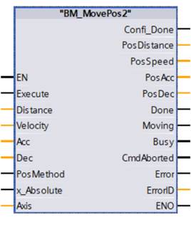
With Execute = TRUE an edge-sensitive execution takes place, whereby
the input values are taken over and the output parameters PosDistance, Pos
Speed, PosAcc and PosDec are written cyclically to the peripheral address set in "Axis" on the
drive is written cyclically to the peripheral address that is set in "Axis" on the corresponding drive. A renewed
command requires a FALSE after a TRUE change at input
Execute, or after the Execute command has been switched on, from the second positioning onwards
a new positioning change of the positioning target is carried out automatically.
An Abort of the active movement command is carried out with BM_Stop2. The execution of the abort is visible at the CommandoAborted output.
Diagram for positive edge and new setpoint execution:
Diagram 1: positive edge Execution
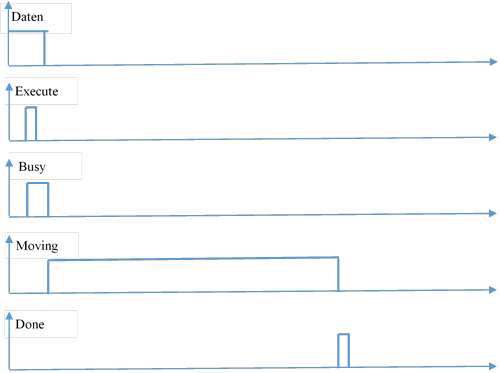
Diagram 2: positive flank execution
Diagram 3: positive edge execution and new set point execution

Zustandskontrolle
über BM_ReadStatus:
Aus Zustand: Standstill,
DiscreteMotion, ContinuousMotion, SynchronizedMotion.
Nach Zustand: DiscreteMotion.
Empfohlene Task: OB1.
Note:
The resulting target position must lie within the positioning distance and can be limited with device-side and software limit switches. If the DiscreteMotion state is exited into another movement state, e.g. ContinuousMotion, a reference run (BM_Home) may have to be carried out afterwards.
A command of "BM_MovePos2" can not be activated until a command of another function module has been successfully executed.
If input parameter PosMethod =0 is set, the Execute command of the block "BM_MovePos2" can not be activated if "BM".AXIS[x].DRIVE.BM_AXIS_STATUS.ParmRW_Active =1. If problems occur, the function block BM_Reset resets
Input Execute:
TRUE: Execution after a positive edge.
1. the input parameters are taken over during an execution of positive Execute edge
2. the input parameters are taken over when input parameter Distance is changed, if Input Parameter Execute = 1.
FALSE: No execution
Input Distance:
Signed Indication of the relative distance or absolute position in increments, With Baumüller drives, one axis revolution corresponds to a resolution of 65536 increments. increments, which are also called user units.
Input Velocity:
Specification as an amount in increments per millisecond. This is the maximum speed of the speed of the target positioning that does not necessarily have to be reached. must be achieved.
minimum: >1 [Inc/ms], maximum: 59999 [inc/ms]
Default: 10 [inc/ms]
Input Acc:
Positive Acceleration as amount in increments per millisecond² .
Minimum: 0.07 [Inc/ms²], maximum: 655.35 [Inc/ms²]
Default: 2.00 [Inc/ms²]
Input Dec:
Negative Acceleration as an amount in increments per millisecond.
Minimum: 0.07 [Inc/ms²], maximum: 655.35 [Inc/ms²]
Default: 2.00 [Inc/ms²]
Input Method:
Via input parameter Method parameters 118.2, 118.10 and 109.1 can be set by the module, if the input Method = 0.
0: 118.2 bit 8 =0 : new setpoint
118.10 : relative or absolute via input parameter Absolute
109.1 : Positioning mode
1: the parameters 118.2 118.10 and 109.1 are set manually via BM_Write or via the operating software ProDrive.
Input Absolute
This input parameter is only activated when the Method input =0,
Absolute = 1: Absolute positioning
Absolute = 0: Relative positioning
Output Confi_Done:
TRUE = Parameter Setting for position target was successfully executed.
FALSE = Command active or not possible.
Output PosDistance:
The parameter writes cyclically to the predefined peripheral address of the drive.
If input parameter Method =0 and Absolute =1, parameter 118.10 =0 is written in the device. This automatically sets the positioning to be carried out absolutely, the input PosDistance is written with the corresponding target position to parameter 118.9. This must be set in the configured as a cyclical parameter in the Siemens project and the corresponding PLC variable must be connected to the PosDistance input.
If the input Absolute =0, the parameter 118.10 =4 is written in the device. This automatically sets the positioning to be carried out relatively. The input PosDistance is written to the parameter 118.16 with the corresponding target position. This must be configured in the Siemens project as a cyclic parameter and the corresponding PLC variable must be connected to the input PosDistance
If input parameter Method = 1, all parameters must be set manually in the device. Further information on this can be found in the chapter on position target setting in the parameter manual of the corresponding device.
Output PosSpeed:
Current speed Setpoint parameter 118.11 of the target position can be configured via Siemens project as a cyclic parameter and corresponds to PLC variable with PosSpeed. In addition, the connected to PosSpeed via a dummy parameter if this parameter is to be set in the device and not changed.
Output PosAcc:
The current acceleration setpoint parameter 118.12 of the target position can be configured via Siemens project as a cyclic parameter and the corresponding PLC variable can be variable to the PosAcc input. In addition, the connected to PosAcc via a dummy parameter if this parameter is to be set in the device and not changed.
Output PosDec:
The current delay setpoint parameter 118.13 of the target position can be configured via Siemens project as a cyclic parameter and the corresponding PLC variable is variable can be connected to the PosDec input. In addition, the connected to PosDec via a dummy parameter if this parameter is to be set in the device and not changed.
Output Done:
TRUE = Positioning was carried out.
FALSE = Command active or not possible.
Output Moving:
TRUE: Target position of the started positioning has not yet been reached
FALSE: not active
Output Busy:
TRUE: the Service communication for parameter read/write is active.
FALSE: not active.
Output CommandAborted:
TRUE: Aborted by a motion control command from BM_Velocity during positioning movement, BM_Stop2 command, or lack of operational readiness at BM_Power.
FALSE: not active
Output Error:
TRUE: on Error in service communication for parameter read/write present. Info an ErrorID valid and Error Info. see S7 description.
FALSE: No error active
Output ErrorID:
the Information from service communication error (for exact info. see S7 description)
In- and Ouput Axis:
Input/output parameters Axis is the number of the controlled bmaXX drive unit.
At the input and output Axis, the BM Motion Control reference of type CPU1500_BM_AXIS_REF is connected. When programming with the data block template "DB5", the variable is used as follows: "BM.AXIS[x] ".
Where "x" is the axle number of the drive.