BM_ReadStatus
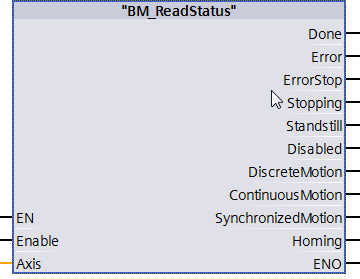
Description
The FC BM_ReadStatus provides the drive status of the BM Motion Control axis.
Attention:
The processing of BM Motion Control Motion commands cannot be made from the errorstop status and requires the availability of the axis via BM_Power.
|
Parameter Input |
Data Type |
Description |
|
Enable |
BOOL |
Update of the status output on every calling |
Parameter Output |
Data Type |
Description |
|
Done |
BOOL |
Output valid; one status is active only |
|
Error |
BOOL |
Error bit, error info ErrorID is valid |
|
Errorstop |
BOOL |
Locking status Errorstop active |
|
Stopping |
BOOL |
Drive is stopped from every movement. Remains active until to the last BM_Stop-instance at the input Execute = TRUE and then changes to Standstill. |
|
Standstill |
BOOL |
Speed is zero. With BM_Power Status = TRUE the MC movements are ready for operation. |
|
Disabled |
BOOL |
The drive status is not in the availability mode |
|
DiscreteMotion |
BOOL |
Drive positions to a positioning target. After finishing it changes to the Standstill status |
|
ContinuousMotion |
BOOL |
Drive moves with a connected speed. |
|
SynchronizedMotion |
BOOL |
Drive moves synchronous to a master position (multi axis commands) |
|
Homing |
BOOL |
Calling up is possible from standstill with BM_Home only and must be interrupted with BM_Stop |
|
Parameters Input and output |
Data Type |
Description |
|
Axis |
UDT |
BM Motion Control Axis Variables |
Description
The BM_ReadStatus command outputs neutral states of the drive movement. The displayed states can be used as transitions (switching condition) to call up movement commands such as BM_Home from standstill. Normally this is not necessary because the movement command states DiscreteMotion, ContinuousMotion and SynchronizedMotion can be interrupted by another movement command.
Call up BM_ReadStatus
from status: all states.
Recommended call up is: OB1.
Note:
BM_ReadStatus especially is used during the set-up phase of the application and should be programmed with BM_Power and BM_Reset at first.
Input Enable:
TRUE: At every call-up the display is updated.
FALSE: No execution and ready to start again.
Output Done:
TRUE: Outputs valid.
FALSE: Reset active or not possible.
Output Error:
TRUE: Error active.
FALSE: No error active.
Output Errorstop:
TRUE: Active.
FALSE: Not active.
Output Stopping:
TRUE: Active.
FALSE: Not active.
Output Standstill:
TRUE: Active.
FALSE: Not active.
Output Disabled:
TRUE: Active.
FALSE: Not active.
Output DiscreteMotion:
TRUE: Active.
FALSE: Not active.
Output ContinuousMotion:
TRUE: Active.
FALSE: Not active.
Output SynchronizedMotion:
TRUE: Active.
FALSE: Not active.
Output Homing:
TRUE: Active.
FALSE: Not active.
Input and output Axis:
UDT type symbolic BM Motion Control axis variable.
During the programming with the data module template DB5 (symbolic "BM") the following symbol text must be written: "BM".AXIS[x] (x is the drive axis number)
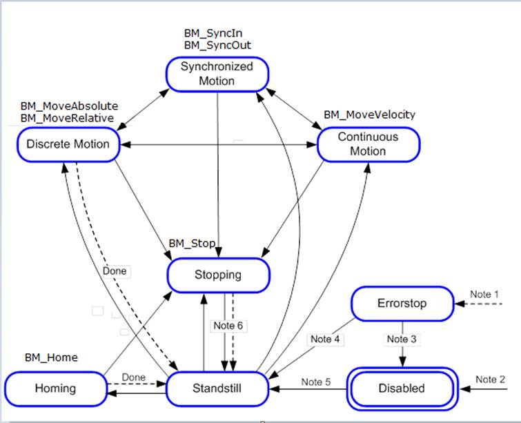
Note 1: From every status. An error in the axis occured.
Note 2: From every status. BM_Power. Enable = FALSE and there is no error in the axis
Note 3: BM_Reset AND BM_Power.Status = FALSE
Note 4: BM_Reset AND BM_Power.Status = TRUE AND BM_Power.Enable = TRUE
Note 5: BM_Power.Enable = TRUE AND BM_Power.Status = TRUE
Note 6: BM_Stop.Done = TRUE AND BM_Stop.Execute = FALSE
Overviewing the state machine of the motion control