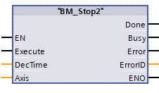
BM_Stop2
Description
The Motion Control FC BM_Stop2
stops the drive axis from the drive states:
Homing, Discrete Motion of BM_MovePos2, Continuous Motion of BM_Velocity2 and
Synchronized Motion
Attention:
Movement commands of synchronized motion in the status Stopping is not possible.
|
Parameter Input |
Data type |
Description |
|
Execute |
BOOL |
Rising edge starts stopping. |
|
DecTime |
REAL |
Delay time to stop for BM_Velocty2; |
|
Parameter Output |
Data Type |
Description |
|
Done |
BOOL |
Stop is executed Done = TRUE as long as Execute = TRUE. |
|
Busy |
BOOL |
Parameter read/write active |
|
Error |
BOOL |
Parameter read/write error |
|
ErrorID |
WORD |
Communication ErrorID-Siemens error list |
|
Parameter Input and output |
Data Type |
Description |
|
Axis |
UDT |
BM Motion Control axis variable |
Description
The following drive states are stopped by the BM_Stop2 command:
Homing, DiscreteMotion with BM_MovePos2, ContinuousMotion with BM_Velocity2 and SynchronizedMotion.
The axis is switched into the stopping status in order to stop it. As soon as the axis was
stopped and the input Execute=FALSE, the axis is switched into the standstill status.
Edge-sensitive execution:
The input Execute must be set from 0 to 1 in order to execute the command. Then
the command is executed and the result Done signals Execute = TRUE at the
input.
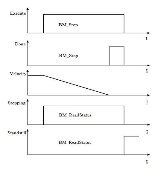
Status message via BM_ReadStatus:
From status: Standstill, Homing, DiscreteMotion, ContinuousMotion, SynchronizedMotion.
To status: Stopping Standstill.
Note:
Stopping to a defined position is not possible.
A command from "BM_Stop" must not be activated before a command from another function block has been not successfully executed.
If an error occurs during the command execution, the error must be reset with "BM_Reset". Function block command will be executed successfully at
Input Execute:
The rising edge (FALSE -> TRUE) initiates the command BM_Stop. The axis is switched into the drive status Stopping and is stopped.
The axis remains in the drive state Stopping until the axis is stopped at the input Execute = TRUE. After this the input Execute = FALSE and the axis change into the drive state from stopping to standstill.
See example 1
input Parameter DecTime:
DecTime is only delay time of BM_Velocity2
Default: 1000[ms]
Minimum: 1[ms]
Maximum: 65000[ms]
DecTime has no influence on BM_MovePos2 and BM_Home.
The delay of BM_Stop2 with FC BM_MovePos2 and BM_Home is the same Delay of the FC
Output Done:
Done = TRUE: Stop is executed at the input Execute = TRUE.
Output Busy:
TRUE: The service communication for the parameter Read/Write is active.
FALSE: Not active.
Output Error:
TRUE: An error at the service communication for the parameter Read/Write is available. See Error Info. Refer to S7 Description.
FALSE: No error active.
Output ErrorID:
The information of service communication error (for detailed information refer to S7 Description)
Input and output Axis:
UDT type symbolic BM Motion Control axis variable.
During the programming with the template data module DB5 (symbolic "BM" must be written with the following symbol text: "BM".AXIS[x] (x is drive axis number).
Example 1: Axis is stopped with BM_Stop – and the input Execute remains TRUE