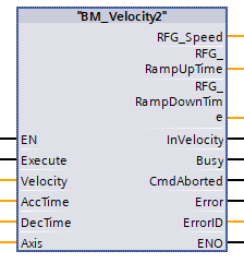
BM_Velocity2
Beschreibung
The BM Motion Control command BM_Velocity2 sets an endless movement with a cyclical data data write in speed control.
|
Parameter Input |
Data Type |
Description |
|
Execute |
BOOL |
Edge sensitive Execution |
|
Velocity |
REAL |
Amount of target speed in % |
|
AccTime |
REAL |
Amount of acceleration time in ms |
|
DecTime |
REAL |
Amount of the decelaration time in ms |
|
Parameter Output |
Data Type |
Description |
|
RFG_Speed |
INT |
Input parameters of the ramp-function generator |
|
RFG_RampUpTime |
UDINT |
Acceleration time Parameters of the ramp function generator |
|
RFG_RampDownTime |
UDINT |
Decelaration time Parameter of the ramp function generator |
|
InVelocity |
BOOL |
Target speed reached |
|
Busy |
BOOL |
Parameter Read/Write active |
|
CommandAborted |
BOOL |
Abort by another Motion Control command, BM_Stop or Errorstop |
|
Error |
BOOL |
Parameter Read/Write error; ErrorID is valid |
|
ErrorID |
DWORD |
Communication ErrorID Siemens error list |
|
Parameter Input and Output |
Data Type |
Description |
|
Axis |
CPU1500_BM_AXIS_REF |
BM Motion Control axis variable |
Description
The command BM_MoveVelocity2 executes a velocity specification with ramp-up encoder. The command switches the axis to the ContinuousMotion state and closes it with with InVelocity = TRUE and remains in the ContinuousMotion state, as long as no other motion command is switched. With Execute = TRUE, an edge-sensitive execution is carried out, whereby the input values are values are accepted and the output parameters RFG_Speed, RFG_RampUpTime and RFG_RampDownTime are cyclically written to the drive periphery address defined by Axis. address is written. A renewed activation of the command requires a FALSE to TRUE change at input Execute, whereby this change must be execution time of the command.
Movement command:
The flank-sensitive execution causes an abort of the active movement command. Execution is aborted with BM_Stop2, missing operational readiness operational readiness or error stop. With the result message only one of the output bits InVelocity, CommandAborted, Busy or Error is active.
Edge-sensitive execution:
To carry out the command the input Execute must be TRUE for one cycle only. Then the command is carried out and the result InVelocity signals if the target speed was reached.

State control via BM_ReadStatus:
From status: Standstill, DiscreteMotion, ContinuousMotion, SynchronizedMotion.
To status: ContinuousMotion
Recommended task: OB1
Note:
An active BM_MoveVelocity2 command can be interrupted by a positioning command according to DiscreteMotion.
The positioning is carried out from the current actual position of the drive. Alternatively,
BM_Stop2 can be used for stopping with subsequent homing via BM_Home.
A command from "BM_Velocity2" must not be activated before a command from another function block has been successfully executed.
And Command should not be activated for "BM".AXIS[x].DRIVE.BM_AXIS_STATUS.ParmRW_Active =1, reset error by BM_Reset.
Input Execute:
TRUE: Edge-sensitive execution, the input parameters are adopted.
FALSE: no execution
Input Velocity:
Specified as an amount in percent( % ) of the max. speed of the drive, with the output InVelocity = TRUE is reached.
Input AccTime:
Acceleration time as Amount in milliseconds for corresponding max. speed of the drive.
Max: 650000[ms].
Min: 1[ms]
Default: 1000 [ms]
Input DecTime:
Deceleration time as Amount in milliseconds for corresponding max. speed of the drive.
Max: 650000[ms].
Min: 1[ms]
Default: 1000 [ms]
Output RFG_Speed:
Input parameter 110.5 of the ramp-function generator. The parameter writes cyclical data to the predefined periphery address of the drive. Parameter 110.5 must be configured as a cyclic parameter.
Output RFG_RampUptime:
Acceleration time Parameter 110.6 of the ramp-up encoder. The parameter writes cyclic to predefined peripheral address of the drive. Parameter 110.6 must be configured as a cyclic parameter in the Siemens project.
Output RFG_RampDownTime:
Return time Parameter 110.7 of the ramp-function generator. The parameter writes cyclically to the predefined peripheral address of the drive. Parameter 110.7 must be configured as a cyclic parameter in the Siemens project.
Output InVelocity:
TRUE: Target speed reached. The axis remains in the ContinuousMotion state.
FALSE : not active.
Output Busy:
TRUE: the service communication for the parameter Read/Write is active
FALSE: not active.
Output CommandAborted:
TRUE: Abort by another Motion Control command, BM_Stop command, Errorstop or missing availability at the BM_Power.
FALSE: not active
Output Error:
TRUE: An error at service communication for parameter Read/Write is existent
for Information on the valid ErrorID and Error information refer to S7 Description..
FALSE: no error active
Output ErrorID:
The information of Service Communication error (for details refer to S7 Description)
Input and Output Axis:
Input/output parameters Axis is the number of the controlled bmaXX drive unit.
At the input and output Axis, the BM Motion Control reference of type CPU1500_BM_AXIS_REF is connected. When programming with the data block template "DB5" the variable is used as follows: "BM.AXIS[x] ".
Where "x" is the axle number of the drive.