MotionControl axis addressing via data module BM
Insert Axis reference data CPU1500_BM_AXIS_REF from library BM_PROFINET_TIA_14bd10 into the PLC data type and insert data block BM into the program block.
Double-click at the function module BM and enter the necessary axis area, parameter HW address and first parameter HW identifier.
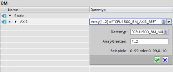
In the "Axis" with data type [ARRAY[x..y]] of CPU1500_BM_AXIS_REF, motion control axis area is entered under the "Array Boundaries".
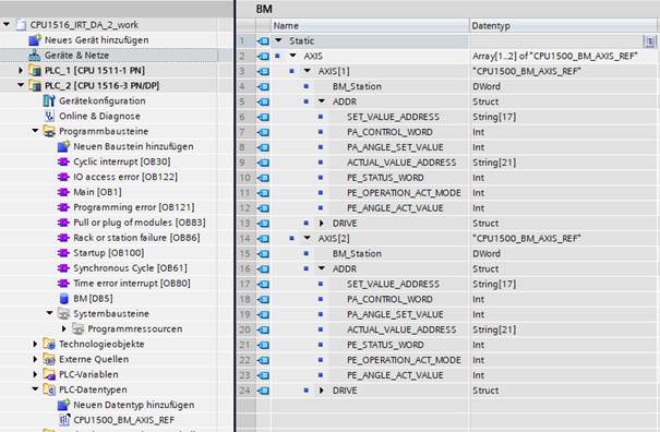
Figure 1: Slave axis setting
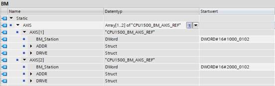
Under Motion Control Axis Number AXIS[] → BM_Station, the setpoint parameter Hardware ID (HW ID) of the bmaXX device is entered first.
BM_Station configuration:
The "BM_Station" defines the controller axis number and the Profinet slave identifier, the type of "BM_Station" is a DWORD (DW#16#HW_LW), (HW: high word , LW: low word).
HW is axis number of the bmaXX unit:
Dual axis device:
Axis1: HW= 0x1000
Axis2: HW= 0x2000
Single axis bmaXX device:
Axis1: HW= 0x1000
LW is hardware identifier(HW identifier) of parameter of first peripheral address, the parameter HW identifier can be found under Properties → System constants. And the value must be converted to hexadecimal.

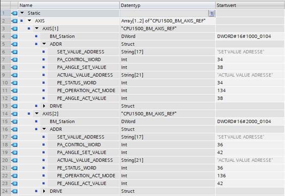
Figure 2: Hardware configuration of CPU1500 (1st setpoint parameter with HW-identifier of 260) with a bmaXX dual axis unit
Parameter Setpoint/actual value Address creation:
Motion Control RT application Addressing
Setpoint Parameter:
Parameter 108.1: Control word (PA_CONTROL_WORD)
Actual Value Parameter:
Parameter 108.3: Status word (PE_STATUS_WORD)
Parameter 109.2: Current Operating Mode (PE_OPERATION_ACT_MODE)
Motion control IRT application with position control Addressing
Setpoint Parameter:
Parameter 108.1: Control word (PA_CONTROL_WORD)
Parameter 108.5: Target angle setpoint (PA_ANGLE_SET_VALUE)
Actual value Parameter:
Parameter 108.3: Status word (PE_STATUS_WORD)
Parameter 109.2: Current Operating Mode (PE_OPERATION_ACT_MODE)
Parameter 18.55: Position Actual value (PE_ANGLE_ACT_VALUE)
Example A:
Motion Control Parameter Addressing with CPU1500 RT Process Data Communication for a Dual Axis Unit
Step 1:
Insert parameters in sequence as setpoints from hardware catalogue of Baumüller module double axis, see figure 3.
Slot No. 1 : Parameter 108.1: Control word1_1 for axis 1
Slot No.2 : Parameter 108.1: Control word1_2 for axis 2
Insert parameters in sequence as actual values from hardware catalogue of Baumüller module double axis
Slot No. 17 : Parameter 108.3 : Status word1_1 for axis 1
Slot No. 18 : Parameter 108.3 : Status word1_2 for axis 2
Slot No. 19 : Parameter 109.2 : Actual mode_1 for axis 1
Slot No. 20 : Parameter 109.2 : Actual mode_2 for axis 2
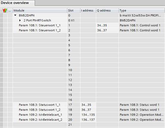
Figure 3: bmaXX Units Dual Axis RT Parameter Addressing of CPU1500
Step 2:
All parameters of double axis number 1 must be set under Properties → General → Assembly parameters, see figure 4.
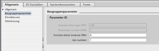
Figure 4: Settings for the Double axis unit Axis number 1
Step 3:
All parameters of double axis number 5 must be set under Properties → General → Assembly parameters, see figure 5.
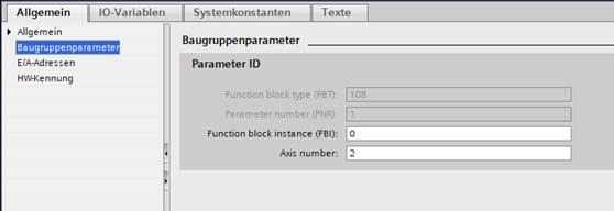
Figure 5: Settings for the Double axis unit Axis number 2
Step 4:
When setting the process data exchange in the RT Bus System, all parameters of the process image must be set under Properties → General → I/O Addresses: Deactivate clock-synchronous operation, set organisation block with OB1 and process image with TPA1 or Automatic update.
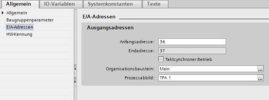
Figure 6: Process image of RT Bus System
Step 5:
Baumüller bmaXX device defines HW-identifier of 1st parameter setpoint or 1st parameter periphery address as Baumüller station hardware identifier for acyclic data communication. The hardware identifier can be found under Properties → 1st parameter setpoint → General → Hardware identifier or under Properties → System constants → 1st parameter setpoint → Hardware identifier.
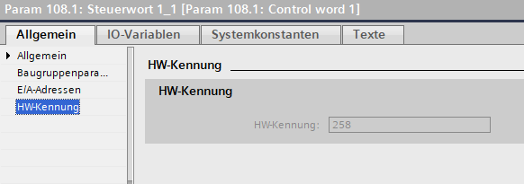
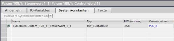
Figure 7: Parameter HW ID
Example B:
Motion Control Parameter Addressing with CPU1500 IRT Process Data Communication for a Dual Axis Unit
Step 1:
Insert parameters in sequence as setpoints from hardware catalogue of Baumüller module double axis, see Figure 8.
Slot no.1 : Param 108.1 : Control word 1_1 for axis 1
Slot no.2 : Param 108.1 : Control word1_2 for axis 2
Slot no.3 : Param 108.5 : Target angle_1 for axis 1
Slot no.4 : Param 108.5 : Target angle_2 for axis 2
Insert parameters in sequence as actual values from hardware catalogue of Baumüller module double axis
Slot No. 17 : Parameter 108.3 : Status word1_1 for axis 1
Slot No. 18 : Parameter 108.3 : Status word 1_2 for axis 2
Slot No. 19 : Parameter 109.2 : Actual mode_1 for axis 1
Slot No. 20 : Parameter 109.2 : Actual mode_2 for axis 2
Slot No. 21 : Param 18.55 : Position actual value angle_1 for axis 1
Slot No. 22: Param 18.55 : Position actual value Angle_2 for axis 2
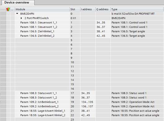
Figure 8: bmaXX devices dual axis IRT parameter addressing of CPU1500
Step 2:
All parameters of double axis number 1 must be set under Properties → General → Assembly parameters, see Figure 4.
Step 3:
All parameters of double axis number 2 must be set under Properties → General → Assembly parameters, see figure 5.
Step 4:
When setting Process Data Exchange in the RT Bus System, all parameters of Process Image must be set under Properties → General → I/O Addresses: Activate clock-synchronous operation, set organisation block with OB61(Synchronous Cycle) and process image with TPA1. Synchronise process image of inputs SYNC_PI and synchronise process image of outputs SYNC_PO must be programmed in OB61, without programming no cyclic data is exchanged, the two process images find extended instructions at Instructions
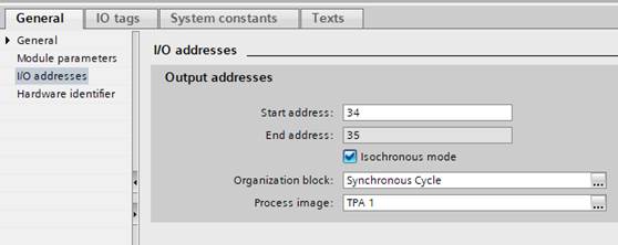
Figure 8: Process image of IRT Bus System
Step 5:
Baumüller bmaXX device defines HW-identifier of 1st parameter setpoint or 1st parameter periphery address as Baumüller station hardware identifier for acyclic data communication. The HW identifier can be found under Properties → 1st Parameter Setpoint → General → HW Identifier or under Properties → System Constants → 1st Parameter Setpoint → HW Identifier, see Figure 7.
Example C:
Motion control axis parameterisation reference under Siemens Tia Portal Baumüller device configuration with CPU1500.
Step 1:
Open the function module BM and set number 1..2 at array limits for motion control axis number 1 and 2
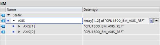
Step 2:
Activate ADDR parameter range under Axis[1] and Axis[2]
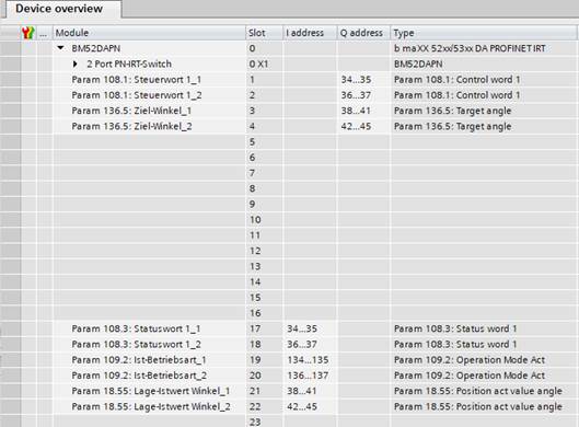
Step 3:
Set double axis number 1 as motion control axis 1 and double axis number 2 as motion control axis 2 and Open bmaXX device parameter window set under Devices&Networks → Device overview.
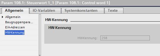
Step 4:
Read the hardware identification of the bmaXX unit from the 1st setpoint value or Param 108.1 Control word 1_1 under Properties → General → HW identification.
HW-Identifier = 258 / 0x102
Step 5:
Sort in all set parameters and start address for motion control axis number 1 and axis 2.
All parameters for motion control axis number 1
Setpoint
Param 108.1: Control word 1_1 and start address: 34
Param 108.5: Target angle_1 and start address: 38
Actual value
Param 108.3: Status word1_1 and start address: 34
Param 109.2: Actual mode_1 and start address: 134
Param 18.55: Position actual value Angle_1 and start address: 38
All parameters for motion control axis number 2
Setpoint
Param 108.1: Control word1_2 and start address: 36
Param 108.5: Target angle_2 and start address: 42
Actual value
Param 108.3: Status word1_2 and start address: 34
Param 109.2: Actual mode_2 and start address: 136
Param 18.55: Position actual value Angle_2 and start address: 42
Step 6:
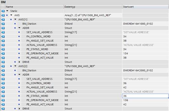
Enter hardware identifier at BM_Station for motion control axis number 1 and 2
Axis [1]: BM_Station = 0x1000_0102
Axis [2]: BM_Station = 0x2000_0102
![]()
![]()
![]()
![]()
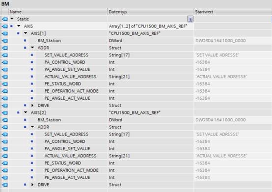
Step 7:
Enter parameter adress in the function module BM
For AXIS[1]:
Setpoint adress:
PA_CONTROL_WORD = 34
PA_ANGLE_SET_VALUE = 38
Actual value adress:
PE_STATUS_WORD = 34
PE_OPERATION_ACT_MODE = 134
PE_ANGE_ACT_VALUE = 38
For AXIS[2]:
Setpoint adress:
PA_CONTROL_WORD = 36
PA_ANGLE_SET_VALUE = 42
Actual value adress:
PE_STATUS_WORD = 36
PE_OPERATION_ACT_MODE = 136
PE_ANGE_ACT_VALUE = 42