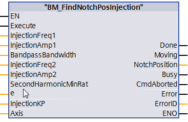
Description
The function "BM_FindNotchPosInjection" carries out a notch position search (parameter 127.008.00) by the injection processing; it is not required that the axis is freely movable in order to carry out this measurement; after measuring successfully the redetermined notch position is displayed.
The redetermined value already is valid in the RAM controller. A takeover into the controller flash can be made with the BM_DataSetHandling.
Further information referring to the notch position search is to be found in the "Parameter manual of the basic unit bmaXX 5000" chapter 3.9.8.
|
Parameter input |
Data type |
Description |
|
Execute |
BOOL |
Edge-sensitive execution |
|
InjectionFreq1 |
REAL |
Injection frequency 1 [1/s] |
|
InjectionAmp1 |
REAL |
Injection amplitude 1 [V] |
|
BandpassBandwidth |
REAL |
Bandpass bandwidth [1/s] |
|
InjectionFreq2 |
REAL |
Injection frequency 2 [1/s] |
|
InjectionApmp2 |
REAL |
Injection amplitude 1 [V] |
|
SecondHarmonicMinRate |
REAL |
Minimum rate second harmonic [%] |
|
InjectionKP |
REAL |
Injection Kp [1/s] |
|
Parameter output |
Data type |
Description |
|
Done |
BOOL |
Notch position search successful |
|
Moving |
BOOL |
Notch position search is running. |
|
Busy |
BOOL |
Parameter Read/write active. |
|
CommandAborted |
BOOL |
Abort by another motion control command, BM_Stop or error stop |
|
Error |
BOOL |
Parameter Read/write error; Error ID is valid |
|
ErrorID |
DWORD |
Communication error ID Siemens error list |
|
Parameter Input and output |
Data type |
Description |
|
Axis |
UDT |
BM Motion Control Axis Variable |
Description
Before activating the command "BM_FindNotchPosRAFS" BM_Power must be switched off and the axis must not be freely movable.
The command "Execute = 1" switches on the Axis notch position search. By an edge-sensitive execution all of the input values are taken over and the command is started at the axis. A new command switching requires a change from FALSE to TRUE at the input "Execute" whereby this change can be carried out at the executing time of the command.
Movement command:
The edge-sensitive execution in switched-off BM_Power state. The execution of abort is aborted with BM_Stop, missing operational readiness or Errorstop. In the result message, only one of the output bits Done, Busy, CommandAborted is active
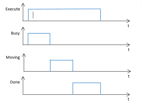
Edge-sensitive execution:
Diagram of an edge-sensitive execution:
Diagram 1:
State
control by BM_ReadStatus:
Off state: Standstill.
After state: -
Recommended task: OB1.
Note:
"BM_Power" and other function block must be switched off and the axis must be freely movable.
A command from "BM_FindNotchPosInjection” must not be activated before a command from another function block has been not successfully executed.
If an error occurs during the command execution, the error must be reset with “BM_Reset”. Function block command will be executed successfully at "BM" .AXIS [x] .DRIVE.BM_AXIS_STATUS.ParmRW_Active = 0.
Input Execute:
TRUE: Edge-sensitive execution, the input parameters are taken over and the notch position search is activated.
FALSE: No execution or resetting of the FC outputs of Error & Error ID.
Input InjectionFreq1:
The parameter InjectionFreq1 can set the frequency of the HF voltage injected in the motor in step 1, unit 1/s.
Minimum: 0.0 [1/s], if 0.0<InjectionFreq1<=0.1
Maximum: 4000.0 [1/s]
Default: 1000.0 [1/s], if InjectionFreq1=0.0
Input InjectionAmp1:
The parameter InjectionAmp1 can set the amplitude of the FH voltage injected in the motor in step 1, unit V.
Minimum: 1.0 [V], maximum: 400.0 [V]
Default: 100.0 [V], if InjectionAmp1 =0.0
Input BandpassBandwidth:
The parameter BandpassBandwidth can set the bandwidth of the filter, which are used to deactivate the HF shares of motor currents Id, Iq.
Minimum: 1.0 [1/s], maximum: 500.0 [1/s]
Default: 50.0 [1/s], if BandpassBandwidth =0.0
Input InjectionFreq2:
With the parameter InjectionFreq2 the frequency of the voltage is set, which is injected during the pole position determination in step 2 in the motor, to cause 180° of ambivalence ; this frequency exclusively takes over the following values to: 62.5 Hz; 125Hz; 250Hz; 500Hz.
Minimum: 0.0 [1/s], if 0.0<Parameter InjectionFreq2<=0.1
Maximum: 1000.0 [1/s]
Default: 250.0 [1/s], if parameter InjectionFreq2=0.0
Input InjectionAmp2:
The parameter InjectionAmp2 can set the amplitude of the HF voltage injected in the motor in step 2.
Minimum: 1.0 [V], maximum: 400.0 [V]
Default: 280.0 [V], if parameter InjectionAmp2=0.0
Input SecondHarmonicMinRate:
The minimum permitted percentage share of the second harmonic I2 of the injected HF current with regard to the fundamental current I1 in the second step
Minimum: 0.0 [%], if parameter 0.0 <SecondHarmonicMinRate =0.1
maximum: 100.0 [%]
Default: 5.0 [%], if Parameter SecondHarmonicMinRate =0.0
Input InjectionKP:
The parameter InjectionKP sets the proportional gain Kp and the integral time Tn of the associated PI compensating controller to the injection process.
Minimum: -1.00000e+10, maximum: +1.00000e+10
Default: 80.0, if parameter InjectionKP =0.0
Output Done:
TRUE: Notch position search is executed. Drive state changes from Enable operation to
Ready-to-switch-on.
FALSE: Not activated.
Output Moving:
TRUE: Notch position search is running.
FALSE: not activated.
Output Busy:
TRUE: The service communication of the parameter Read/write active.
FALSE: Not activated.
Output CommandAborted:
TRUE: Abort due to another motion control command, BM_Stop command, error stop or a missing operating availability to BM_Power.
FALSE: Not activated.
Output Error:
TRUE: An error at the service communication of the parameter Read/write is available. Information to error ID is valid and error information, refer to S7 in the manual.
FALSE: No error activated.
Output ErrorID:
The information of service communication error (detailed information refer to S7 in the manual)
Input and output Axis:
Symbolic BM Motion Control axis variable of an UDT type.
While programming the data module template DDB5 (symbolic "BM") it is to be written with the following symbol text: "BM".AXIS[x] (x is drive axis number).