


General description
Example overview diagram for 2 motors in master-slave connection (with a quadruple multiple winding):
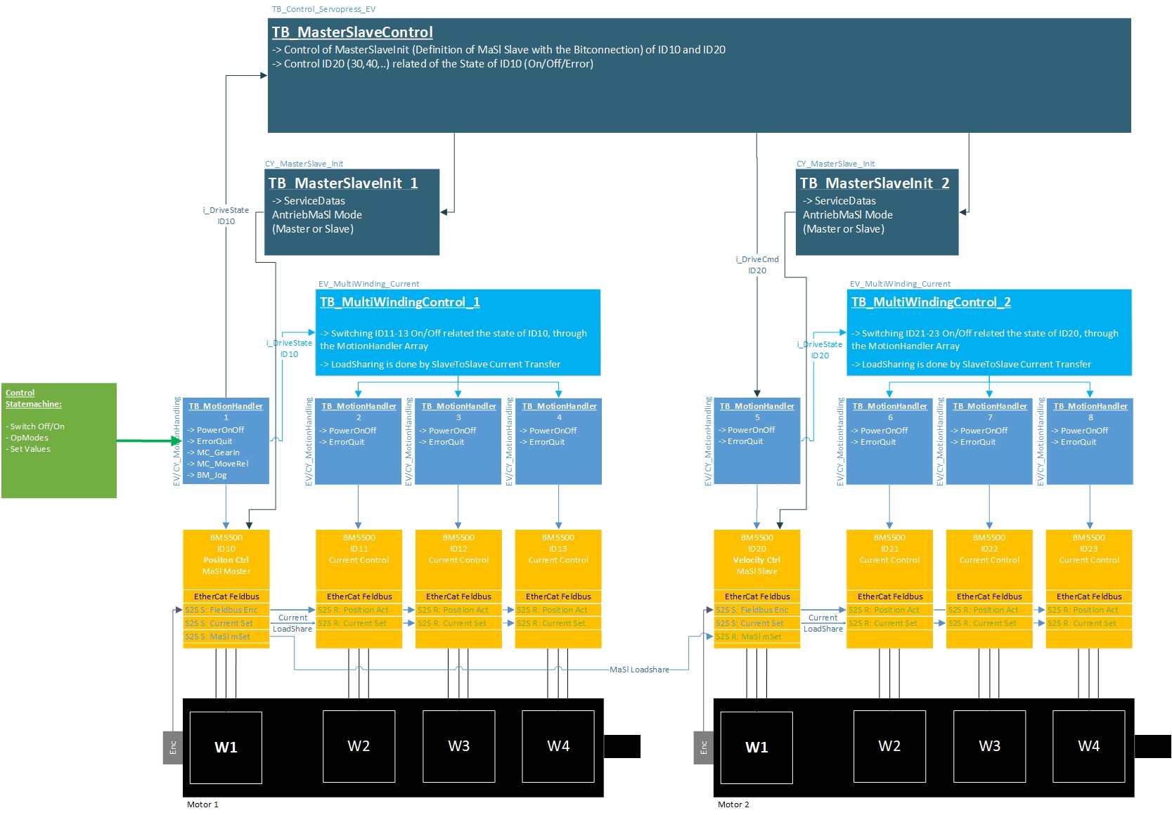
The MotionHandler[1] is the MasterSlave Master.
The array numbers are referred to by the MasterSlaveControl function block. In the example shown below, the a_MotionHandler[5] is the MasterSlave Slave.
The MultiWinding function block also refers to these defined array numbers.
| Motor | Motor 1 | Motor 2 | ||||||
| Winding | M1 W1 | M1 W2 | M1 W3 | M1 W4 | M2 W1 | M2 W2 | M2 W3 | M2 W4 |
| a_MC_Axis_Array[..] => Motion allocation |
1 | 2 | 3 | 4 | 5 | 6 | 7 | 8 |
| a_MotionHandler[..] => MotionHandler allocation |
1 | 2 | 3 | 4 | 5 | 6 | 7 | 8 |
| Function | Master Slave MASTER |
Master Slave SLAVE |
||||||
| w_MaSl_Selection | 0 (Bit 0) |
0 | 0 | 0 | 1 (Bit 4) |
0 | 0 | 0 |
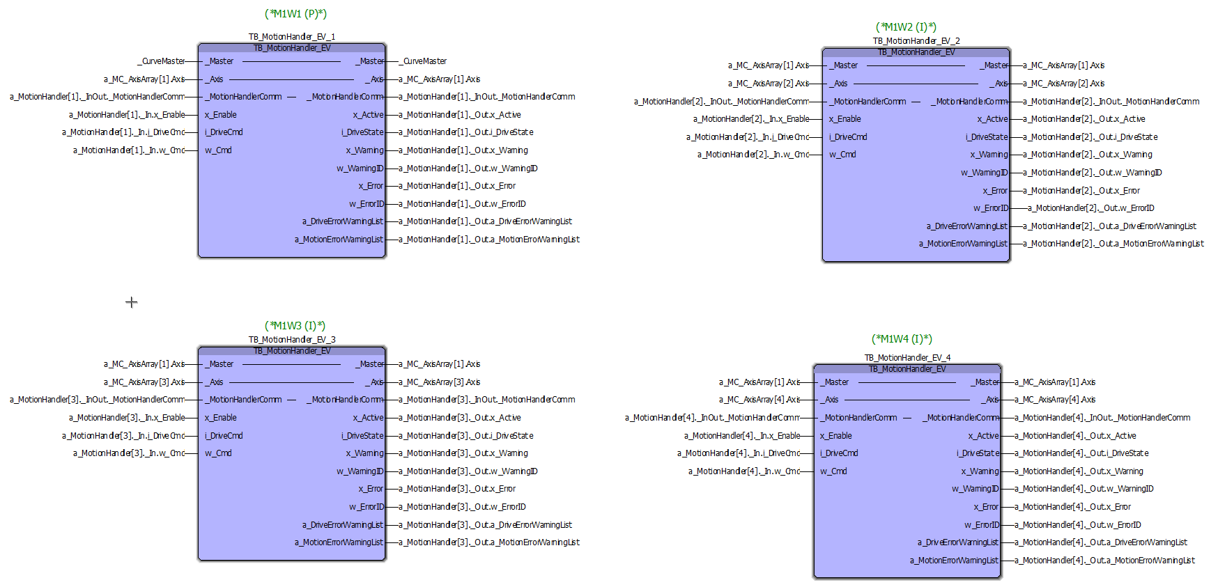
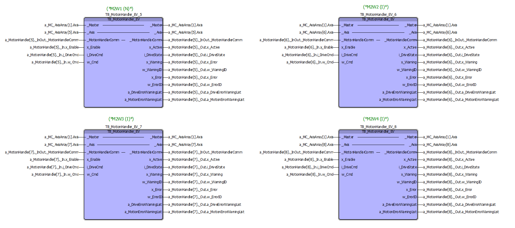
Wiring example of the various function blocks:
MotionHandler Motor 1 (Quadruple winding)
MotionHandler Motor 2 (Quadruple winding)
MasterSlaveControl:
=> a_MasterSlaveInit: The TB_MasterSlaveInit function blocks can be controlled via this. This is done internally via the numbers. These must be assigned according to the table above.
=> a_MotionHandler: The i_DriveState of the MasterSlaveMaster ([1]) is read in via the array, and the MasterSlave slave(s) is/are controlled depending on this. This is defined via the bit strip w_MaSl_SlaveSelection.
To make this all work, the numbers must be assigned as in the example and the table above.

TB_MultiWindingControl:
Wiring of the a_MultiWinding array:
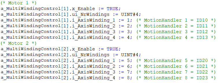
The numbers of the windings correspond to the array numbers of the a_MotionHandler array (see table above).
The MotionHandlers can then be controlled via the a_MotionHandler array connected to the function block.
