


General description
Digital In and Outputs:
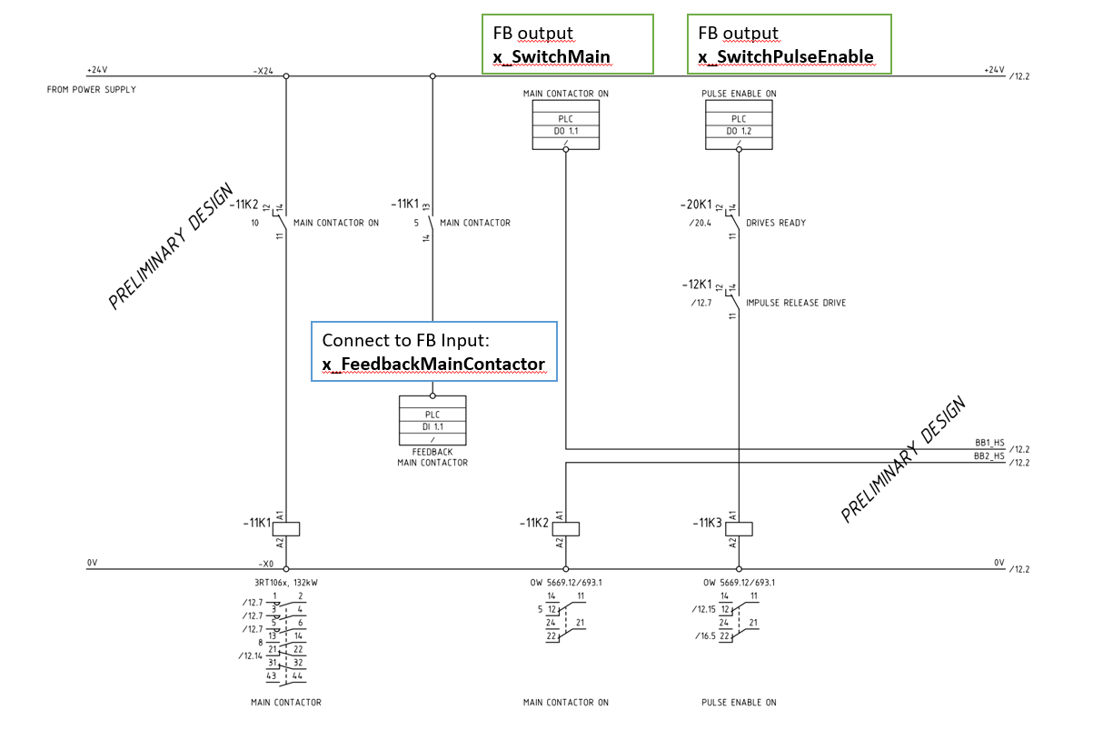
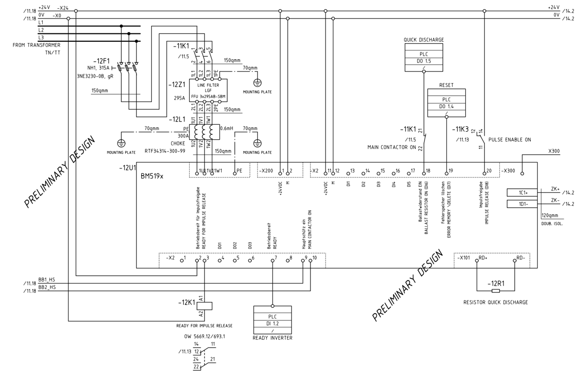
The following wiring diagram, shows an example for the output connection of the AFE.
This wiring is necessary, that the function block can control the AFE.
The function block controls the Main Switch and the Pulse Enable input through the external wiring.
The PLC Coupler IO-cards shown as DI1.1, DO1.1 and DO1.2. This EBus coupler must be configured in Promaster,
the hardwired signals needed to be wired, and the PLC variables of the coupler need to be connected to the function block.
Wiring plan example:
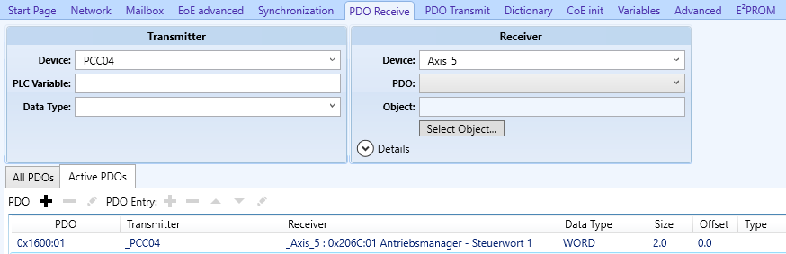
PDO Mapping:
To control the AFE, additional to the wiring above, some PDOs need to insert in ProMaster:
PDO Receive: 0x206C:01 (Controlword)
PDO Transmit: 0x2082:03 (DC-link act value), 0x206C:06(Statusword)
![]()