


General description
Either only distances or distances and lengths can be measured. The latched or saved measured values and the actual angle values of the encoder must be read cyclically. For this purpose, the corresponding parameters must be mapped.
With b maxx 4000, they depend on the encoder used:
| Encoder | Parameter | Number | Comments |
|---|---|---|---|
| 1 | Encoder 1 angle actual value, 32 bits | 60fb.0a | 32-bit angle. |
| 1 | Measured value revolutions pos. edge, 32 bits | 0x4246 (P582) | Use of the lower 16 bits(*) |
| 1 | Measured value angle pos. edge, 32 bits | 0x4245 (P581) | Use of the upper 16 bits(*) |
| 1 | Measured value revolutions neg. edge, 32 bits | 0x4248 | Use of the lower 16 bits(*) |
| 1 | Measured value angle neg. edge, 32 bits | 0x4247 | Use of the upper 16 bits(*) |
| 2 | Encoder 2 angle actual value | 0x4191 | 32-bit angle |
| 2 | Measured value revolutions pos. edge, 32 bits | 0x424a | Use of the lower 16 bits(*) |
| 2 | Measured value angle pos. edge, 32 bits | 0x4249 | Use of the upper 16 bits(*) |
| 2 | Measured value revolutions neg. edge, 32 bits | 0x424c | Use of the lower 16 bits(*) |
| 2 | Measured value angle neg. edge, 32 bits | 0x424b | Use of the upper 16 bits(*) |
Since d_TP_PosLH and d_TP_PosHL must be both a 16-bit revolution and 16-bit angle, the measured values are still to be shifted and ORed.
(*) Example combining of values in FUP:
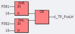
P581 and P582 are the parameters of the drive that are read cyclically.
If using the bmaXX 5000 series, the mapping depends from the choosen Axistype (Singleaxis: Offest 0x2000 / Doubleaxis: Axis 1 0x2000 / Axis 2 0x4000), the used Encoder (Enc 1 or Enc 2) and the used digital Input (MT1 or MT2).
| Encoder | Parameter | Number | Comments |
|---|---|---|---|
| 1 | Encoder 1 angle actual value, 32 bits. | 60fb.0A | 32 Bit angle |
| 2 | Encoder 2 angle actual value, 32 bits. | 68fb.0A | 32 Bit angle |
| Toucheprobe 1 input: | |||
| 1 | Measured value revolutions pos. edge, 32 bits (TP1) | 207c.05 | Use of the lower 16 bits(*) |
| 1 | Measured value angle pos. edge, 32 bits (TP1) | 207c.06 | Use of the upper 16 bits(*) |
| 1 | Measured value revolutions neg. edge, 32 bits (TP1) | 207c.07 | Use of the lower 16 bits(*) |
| 1 | Measured value angle neg. edge, 32 bits (TP1) | 207c.08 | Use of the upper 16 bits(*) |
| 2 | Measured value revolutions pos. edge, 32 bits (TP1) | 207c.11 | Use of the lower 16 bits(*) |
| 2 | Measured value angle pos. edge, 32 bits (TP1) | 207c.12 | Use of the upper 16 bits(*) |
| 2 | Measured value revolutions neg. edge, 32 bits (TP1) | 207c.13 | Use of the lower 16 bits(*) |
| 2 | Measured value angle neg. edge, 32 bits (TP1) | 207c.14 | Use of the upper 16 bits(*) |
| Toucheprobe 2 input: | |||
| 1 | Measured value revolutions pos. edge, 32 bits (TP2) | 207c.09 | Use of the lower 16 bits(*) |
| 1 | Measured value angle pos. edge, 32 bits (TP2) | 207c.0A | Use of the upper 16 bits(*) |
| 1 | Measured value revolutions neg. edge, 32 bits (TP2) | 207c.0B | Use of the lower 16 bits(*) |
| 1 | Measured value angle neg. edge, 32 bits (TP2) | 207c.0C | Use of the upper 16 bits(*) |
| 2 | Measured value revolutions pos. edge, 32 bits (TP2) | 207c.15 | Use of the lower 16 bits(*) |
| 2 | Measured value angle pos. edge, 32 bits (TP2) | 207c.16 | Use of the upper 16 bits(*) |
| 2 | Measured value revolutions neg. edge, 32 bits (TP2) | 207c.17 | Use of the lower 16 bits(*) |
| 2 | Measured value angle neg. edge, 32 bits (TP2) | 207c.18 | Use of the upper 16 bits(*) |
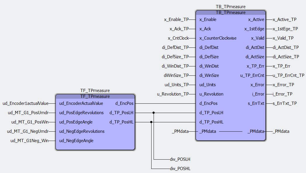
For not doing the Bit shifting manually, there is a function block available, which does this internally (Details are written in the help file of TF_TPmeasure).
Example of connection:
Distance measurement:
Mode0: The measured position of the edge (in format 16:16) is connected to input d_TP_PosLH.
Mode1: The measured position of the edge (in format 16:16) is connected to input d_TP_PosHL.
The first edge is sought once the module is started. If an edge cannot be found without two lengths (di_DefDist), the module cancels with an error message.
If a mark cannot be found in the window during operation, the last measured distance is output at the top edge of the window. At the same time, x_TP_Err = TRUE and u_TP_ErrCnt is incremented. The user decides whether the previous values can be used in case mark detection is missing or whether the machine must be stopped!
Function (Mode 0):
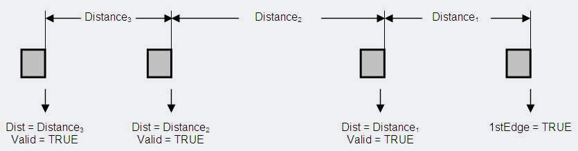
Behavior of the module:
| Event | Result | Comments |
|---|---|---|
| Starting of the module | x_1stEdge=FALSE x_Valid=FALSE x_TP_Err=FALSE di_ActDist=-1 |
|
| First edge is detected | x_1stEdge=TRUE x_Valid=FALSE x_TP_Err=FALSE di_ActDist=-1 |
x_1stEdge remains TRUE. |
| Next valid edge is detected | x_1stEdge=TRUE x_Valid=TRUE x_TP_Err=FALSE di_ActDist=distance |
x_1stEdge remains TRUE. x_Valid remains TRUE, until acceptance has been acknowledged (x_Ack = TRUE. u_TP_ErrCnt is reset. di_ActSize is set to -1 when x_Ack = TRUE. |
| No edge detected in window | x_1stEdge=TRUE x_Valid=TRUE x_TP_Err=TRUE di_ActDist=last distance |
Output of the last measured distance to the top edge of the window. x_Valid and x_TP_Err remain TRUE until acceptance has been acknowledged (x_Ack = TRUE). u_TP_ErrCnt is incremented.di_ActDist is set to -1 when x_Ack = TRUE. |
Distance and length:
In this operating mode, the length (distance from front to back edge) is measured in addition to the distance of the (front) edges.
Mode2: The measured position of the front edge (in format 16:16) is connected to the d_TP_PosLH input, and the measured position of the back edge (in format 16:16) is connected to the d_TP_PosHL input.
Mode3: The measured position of the front edge (in format 16:16) is connected to the d_TP_PosHL input, and the measured position of the back edge (in format 16:16) is connected to the d_TP_PosLH input.
Function (Mode 2):
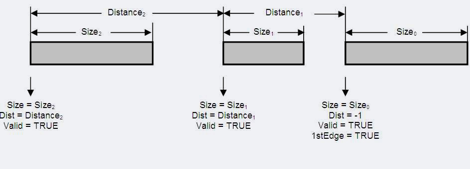
Behavior of the module:
| Event | Result | Comments |
|---|---|---|
| Starting of the module | x_1stEdge=FALSE x_Valid=FALSE x_TP_Err=FALSE di_ActDist=-1 di_ActSize=-1 |
|
| First front edge is detected | x_1stEdge=FALSE x_Valid=FALSE x_TP_Err=FALSE di_ActDist=-1 di_ActSize=-1 |
A valid back edge is sought. If a valid back edge is not found, a front edge is sought again (interfering edge detection). |
| First valid rear edge is detected | x_1stEdge=TRUE x_Valid=TRUE x_TP_Err=FALSE di_ActDist=-1 di_ActSize=length |
x_1stEdge remains TRUE. x_Valid remains TRUE, until acceptance has been acknowledged (x_Ack = TRUE. u_TP_ErrCnt is reset. di_ActSize is set to -1 when x_Ack = TRUE. |
| Next valid front edge is detected | No response | |
| Next valid rear edge is detected | x_1stEdge=TRUE x_Valid=TRUE x_TP_Err=FALSE di_ActDist=distance di_ActSize=length |
x_1stEdge remains TRUE. x_Valid remains TRUE, until acceptance has been acknowledged (x_Ack = TRUE). u_TP_ErrCnt is reset. di_ActDist and di_ActSize are set to -1 when x_Ack = TRUE. |
| No valid front edge detected | x_1stEdge=TRUE x_Valid=TRUE x_TP_Err=TRUE di_ActDist=max. dist. di_ActSize=min. leng. |
Output of a default mark with min. length and max. distance x_Valid and x_TP_Err remain TRUE, until acceptance has been acknowledged (x_Ack = TRUE). di_ActDist and di_ActSize are set to -1 when x_Ack = TRUE. |
| No valid back edge detected | x_1stEdge=TRUE x_Valid=TRUE x_TP_Err=TRUE di_ActDist=max. dist. di_ActSize=min. leng. |
Output of a virtual mark with min. width and max. distance x_Valid and x_TP_Err remain TRUE, until acceptance has been acknowledged (x_Ack = TRUE). di_ActDist and di_ActSize are set to -1 when x_Ack = TRUE. |