Basics: Control process
Read min.

The control process is a system whose control variables are changed or kept constant by the controller. This can be, for example, a motor including the machine driven by it. Control variables can be parameters such as speed, which are predefined by a control system and, after comparison with the data from a measuring instruction (e.g. a rotary encoder on the motor), are adjusted by the controller.
Precisely analyzing the controlled system and optimally setting the controller to it is an important factor in the process optimization of industrial machines. Large potential exists here to reduce operating and maintenance costs significantly.
The following glossary entry contains:
Definition
Controlled system is an abstract term that describes what lies between the measuring instrument and the controller within a control circuit. This means, in physical terms it means the systems whose control variables are to be adjusted, e.g. a servomotor. The system in control engineering does not merely involve the purely physical variable, but also includes other parameters, which reflect the behavior of the controlled system in practice.
Function based on a speed controlled system
In order to understand what the controlled system is, the overall system is represented by way of example by a servo drive with regard to the speed control. The most important components in this simplified, schematic overview are:
- Rotary encoder (e.g. resolver)
- Software
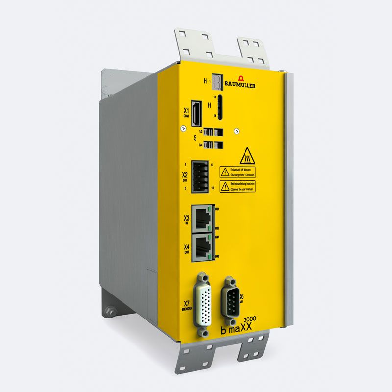
- Servo controller
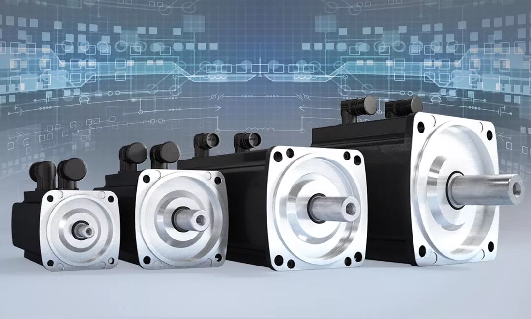
- Servo motor
1. Rotary encoder (e.g. Resolver):
The component is connected directly to the motor shaft and records its rotation. Inside, there is a rotor winding and on the outside there are two stator windings arranged at right-angles. By supplying current, the flux between the stators and rotor can be measured and converted into a signal, which reflect the rotation in relation to time, i.e. the speed. Here the actual value is determined.
2. Software:
In the connected software, digital set values can be set, which ensure smooth and efficient operation of the drive or the machine driven by it.


3. Servo controller:
The controller synchronizes the set values, which have been parameterized in the servo-controller by means of a software tool, and the actual values of the rotary encoder (e.g. resolver). If discrepancies occur here, a readjustment can be made.
Together, the control circuit is created. A cycle is thus formed via the motor, the rotary encoder measuring instrument and the controller, in which permanent synchronization of the set and actual values occurs – the speed (controlled variable) can therefore be controlled precisely.
The controlled system is the subarea between the servo-controller and rotary encoder (e.g. resolver) and thus the system whose controlled variable is to be influenced. In this case, the controlled system is, for example, the servomotor (4), whose speed is controlled. However, in pure physical terms, it does not only involve the motor but also its behavior. Part of the controlled system is therefore that which influences the speed effectively – for example, friction resistances and their effects on the behavior of the motor, which as a consequence is non-linear.
Step response of the controlled system
The controller predetermines a step changed in the manipulated variable. The step response is the system’s response to this in relation to time. There are different types of controlled systems. Among other things, a differentiation is made between the controlled system with balancing and the controlled system without balancing. In the first case the aim is to achieve a uniform output value on a specific level with a constant input. Without balancing, the output is steadily increasing. The controlled system with dead time is also an example in practice. This describes delays of the signal, for example, through its run times.
Analysis and optimization in practice
A precise analysis of a controlled system and an optimized adjustment of the parameters based on this can effectively contribute to saving costs and reducing standstill times to a minimum. Intelligent drive technology from Baumüller clearly focuses on this.
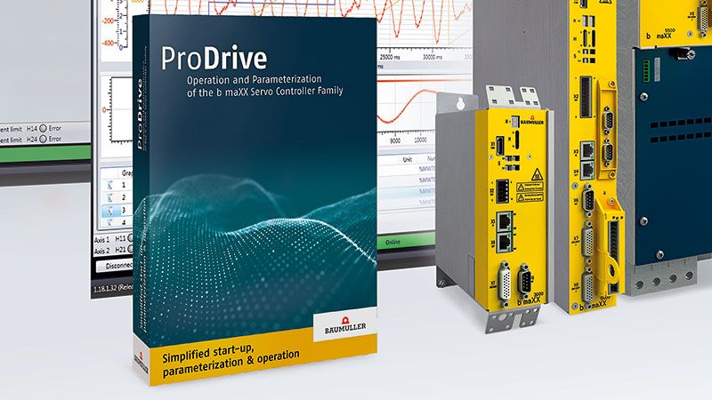
Our ProDrive parameterization and diagnostic tool is optimally designed for this and allows efficient self-optimization of the controller parameters for your individual controlled system.
Summary
The controlled system is an abstract variable, which describes a system to be controlled including all properties and behaviors. As part of the control circuit, it lies between the controller itself and the measuring instrument, which provides the actual values of the controlled variables. The system itself can be optimized by a well thought out design, as is the case in Baumüller servomotors. However, in practice, this is also highly influenced by the systems driven by it. The exact analysis of the specific behavior – for example, under maximum load or under certain speeds – and the corresponding adjustment of the control behavior are essential components of the process optimization and thus of the cutting of operating costs.

Matthias Beetz
Training Engineer Academy I Baumüller Nürnberg GmbH


