English
{loadposition language-mobile}

Basics: Servo Drive – Structure, Function, and Design

Matthias Beetz, Baumüller Nürnberg GmbH

Read min.

Baumüller servo drive: Servo motors, b maXX servo controllers, control units, and software as a drive system

The term "servo drive" has two meanings. In the narrowest sense, it refers to the electronic drive unit that controls the motor — that is, the servo controller alone. Broadly speaking, it refers to the entire controlled axis consisting of a servo motor, servo controller, encoder system, and — where the application requires it — a transmission. It is only through this interaction that the servo drive truly comes into its own: position, speed, and torque can be controlled simultaneously — and highly dynamically.

This basic introductory article takes a broad perspective, since the function and design can only be understood in the context of the entire system. Anyone who dimensions a servo drive, is never just designing a single device — they’re always designing the entire axis, including the load and the mechanical system. Baumüller supplies this axis from a single source, from the servo motor to the servo controller to the control unit.

Definition – What Is a Servo Drive?

A servo drive is an electronically regulated drive that moves an axis with high dynamics and precision to a position, speed, or torque. Compared to an uncontrolled drive, it achieves a whole new level of accuracy, dynamics, and acceleration. That is exactly what makes it the standard wherever a machine needs to operate quickly and with repeatability. The terms "servo axis" and, for a group of multiple axes, "servo system" are also commonly used.

The decisive feature is the closed control loop. A servo drive continuously measures the actual position of the axis and its speed, compares these actual values with the control unit's setpoints, and corrects any deviation.

Without this feedback, the drive is controlled (by an open loop control) but not regulated (by a closed loop control), and is therefore not a servo drive. Mastering this process with precision is the core competency that Baumüller has been developing for over 90 years.

This does not refer to the small actuators that are also called "servo drives" in model making, building automation, or as pneumatic valve actuators. This article discusses electric servo drives in industrial automation.

Servo Drive, Servo Motor, and Servo Controller: The Differences

The servo drive is the system; the servo motor is the actuator within it; and the servo controller is the electronics that control it. These three levels are often conflated in everyday life, but they must be clearly distinguished for the design.

The servo motor converts electrical power into mechanical power. In servo drive technology, it is usually a permanently excited synchronous motor with a slim construction and high overload capacity; in some cases, it is also a linear or torque motor. Baumüller offers its servo motors in four series, ranging from the dynamic DSD2 and the compact DSC to the DSH1, which features exceptionally low cogging torque for maximum precision.

The servo controller supplies power to the motor and closes the control loops. Depending on the manufacturer, the same device is also referred to as a servo converter or servo amplifier; at Baumüller, this class of devices is known as b maXX.

Structure – the Components of a Servo Drive

A servo drive consists of five modules that work together as a functional unit:

The servo motor generates torque and motion; synchronous, linear, or torque motor. In industry, these are consistently designed as AC servo drives; DC versions with brushes are now only used in existing systems.

The servo controller redirects power to the motor, closes the current, speed, and position control loops, and provides safety functions ranging from STO (Safe Torque Off) to SS1 and safe positioning, which can be transmitted via FSoE (FailSafe over EtherCAT).

The sensor system reports back on position and speed; for example, at Baumüller as a resolver or a digital encoder with EnDat 2.2, Hiperface DSL, SSI, and many others.

Mechanical system: transmission, spindle, rack, chain, belt, or clutch; transmits motion to the load

The higher-level (superordinate) control specifies the motion profile and process; usually a PLC or motion control system.

Servo drives in a multi-axis system: control unit, horizontally stacked (daisy-chained) servo controllers with a common DC link, and the associated servo motors

Servo drives in a multi-axis system: control unit, horizontally stacked (daisy-chained) servo controllers with a common DC link, and the associated servo motors

Baumüller manufactures its servo motors in seven sizes ranging from 28 to 132, with rated torques from 0.6 to 715 Nm, and available in uncooled, air-cooled, or liquid-cooled (water or oil) versions. This allows the motor to be precisely tailored to the axle based on its size, windings, and cooling system.

The mechanical system is definitely part of it, even if it is easy to overlook. A transmission adapts speed and torque to the load and reduces its inertia in proportion to the square of the transmission ratio, but introduces clearance and flexibility into the axle. Both of these factors limit the achievable positioning accuracy, regardless of how good the motor and controller are. Servo gearboxes are therefore designed with low backlash and can handle higher loads than standard gearboxes. With linear axes, this detour is eliminated: A linear motor moves the carriage directly, without a spindle and without gear backlash — though at a higher cost.

Function – the Block Diagram

In terms of control, a servo drive is a cascade of three nested closed loop controls. The block diagram shows them.
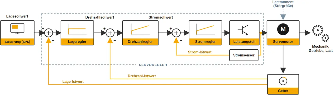
Block diagram of a servo drive: position, speed, and current control loops in cascade (cascade control)

Block diagram of a servo drive: position, speed, and current control loops in cascade (cascade control)

The process starts on the left. The control unit sets a position setpoint. At the summation point, the actual value of the encoder is subtracted from this; what remains is the deviation. The position controller converts this into a speed setpoint; the speed controller converts it into a current setpoint; and finally, the current controller controls the power module, which supplies the servo motor with current and voltage. The encoder feeds back the position and speed data, and the loop is closed. A varying load torque acts as a disturbance variable on the motor; the closed-loop control system continuously compensates for it.

Why this tiered structure? Because every internal closed loop control must operate at least as fast as the one surrounding it; otherwise, the axis will vibrate. The internal current control is therefore the fastest: Baumüller's b maXX 3300 calculates it in 62.5 µs, while speed and position control each run at 125 µs.

What the controller is actually dealing with — that is, the motor, transmission, load, and their friction — is referred to in control engineering as the closed loop controlled system. During commissioning, Baumüller automatically tunes the controller and system using the ProDrive tool and the Smart Tuning function, rather than searching for each parameter manually.

Servo drive, frequency converter, or stepper motor?

A servo drive is not always the right choice. The decision depends on whether an axis needs to be positioned or just rotated.

Servo drive

Drive with frequency converter

Stepper motor drive

Regulation:
closed-loop control

Regulation:
usually open (U/f control unit)

Regulation:
open, usually without feedback

Feedback:
Encoder on the motor

Feedback:
usually none

Feedback:
none (except closed-loop variants)

Positioning:
high-precision, with repeatability down to the range of angular seconds

Positioning:
not provided for

Positioning:
exact, but without actual value feedback

Torque when stopped:
full standstill torque

Torque when stopped:
near zero for U/f control unit

Torque when stopped:
holding torque present

Overload capacity:
high, up to a factor of 3 or more

Overload capacity:
around 1.5

Overload capacity:
low

Typical use:
Positioning and synchronous axes

Typical use:
Pumps, fans, conveyor belts

Typical use:
simple adjustable axes

Costs:
high

Costs:
low

Costs:
low to medium

For a pump that rotates at a constant speed, a servo drive would be overkill; a stepper motor, on the other hand, is often the more cost-effective solution for moderate requirements — but there’s a catch: if it loses steps under load, no one will notice because there’s no feedback.

As soon as high acceleration, repeatability, or synchronized operation of multiple axes is required, a servo drive is essential; Baumüller’s b maXX family covers the entire performance range in this area.

Characteristics and Design

An important characteristic is overload capacity. A servo motor can briefly deliver many times the torque it can sustain, and that is exactly what it needs when accelerating. The exact value of this multiple depends on the size: Small axes can reach three times their standstill torque (M0) or more, while large drives have lower values because their power electronics are designed to operate closer to their continuous-duty limit. In each case, the weaker link — either the motor or the converter — acts as the limiting factor. The synchronous motor characteristic curve shows the relationship between torque and speed across the entire operating range.

In the design, it is not the peak value that matters, but rather the averaged torque over the machine cycle; otherwise, the drive will be overdimensioned. Equally important is the ratio of load inertia to motor inertia. A ratio of around 5:1 is considered non-critical; with stiff mechanical system and a well-tuned controller, even a 10:1 ratio can be managed. If it gets significantly larger, the load may end up moving the motor rather than the other way around, and the axle tends to vibrate. When the load becomes too heavy, a transmission helps by transferring its moment of inertia to the motor side.

No one has to do this calculation by hand. Using the sizemaXX design tool, Baumüller dimensions the axis step by step, avoids overdimensioning, and identifies potential savings in the drive. This not only saves time, but also keeps energy consumption low during subsequent operation.

Servo Drives in Automation Technology

Servo drives are used wherever a machine needs to operate quickly, with high repeatability, and in sync with other axes.

Servo Drives in Automation Technology: Applications in Printing, Packaging, Textiles, and Robotics

Servo Drives in Automation Technology: Applications in Printing, Packaging, Textiles, and Robotics

In printing presses, the inking units operate without a mechanical main drive shaft. Each roller is equipped with its own servo drive, and an electronic shaft ensures synchronous operation. Even the slightest deviations between the axes will later show up as misregistration in the printed image. In injection molding in plastics processing, on the other hand, the injection axis must follow a predefined pressure and speed profile — and this profile must be identical for every shot — otherwise component quality will vary.

Typical applications include:

In a multi-axis servo drive system, the servo controllers are networked via a real-time fieldbus such as EtherCAT so that all axes operate in sync; the high-level motion control system coordinates them. Baumüller’s b maXX servo converters, which cover a range up to 400 kW, demonstrate which series is suitable for which power class.

This coordination does not necessarily have to be handled by a separate PLC. Modern servo controllers are increasingly taking on control tasks themselves: At Baumüller, the integrated drivePLC in the servo controller can act as an EtherCAT master to control additional axes, eliminating the need for a higher-level controller depending on the application. This saves costs and avoids dead times on the fieldbus. For more on this, see the article on intelligent drive technology.

Summary – everything at a glance

A servo drive refers to the controlled axis as a whole: the servo motor, servo controller, encoder, and mechanical system. Its performance stems from the cascade of current, speed, and position control circuits, and it can be verified — rather than merely claimed — based on overload capacity and cycle times. When designing, the averaged torque and the inertia ratio are the determining factors, not the peak value listed in the catalog.

From an economic standpoint, servo technology pays off in applications where cycle time and precision are the deciding factors. Their benefits go beyond mere positioning. Baumüller servo motors achieve efficiencies of over 90 percent — up to 96 percent at peak — and in multi-axis systems, braking energy can be reused via a common DC link instead of being wasted. When it comes to a system's energy efficiency, this is often a more effective lever than the motor itself.

Baumüller supplies servo drives as a complete system consisting of a motor, converter, control unit, and software. If you have any questions about the design of your axis, please feel free to contact us directly at any time.

Frequently Asked Questions About Servo Drives

What is a servo drive?

A servo drive is a controlled drive axis consisting of a servo motor, a servo controller, a sensor system, and, if necessary, a transmission. It controls position, speed, and torque in a closed-loop control and meets high dynamics and accuracy requirements. Typical applications include machine tools, packaging systems, printing presses, and robots.

What is the difference between a servo drive and a servo motor?

The servo motor is a component of the servo drive. It generates torque and motion, but can only do so in a controlled manner if a servo controller and a sensor system are added. The term "servo drive" describes this complete unit—that is, the entire axis, including the mechanical system.

How does a servo drive work?

A servo drive operates using three cascaded closed loop controls. The position controller converts the position deviation into a speed setpoint; the speed controller converts it into a current setpoint; and the current controller sets the torque. A sensor on the motor provides continuous position and speed feedback, allowing the drive to correct deviations within milliseconds.

What is the difference between a servo drive and a frequency converter drive?

A frequency converter controls a motor's speed, mostly without feedback and is suitable for uniform motion, such as in pumps or fans. A servo drive operates with sensor feedback, positions with high precision, maintains full torque at a standstill, and can briefly withstand a multiple of its standstill torque (M0).

How is a servo drive designed?

What matters is the torque averaged over the machine cycle, not the peak value. In addition, there is the load-to-motor inertia ratio, which remains uncritical up to around 5:1 — and even up to 10:1 with a rigid mechanical system. At Baumüller, the sizemaXX design tool handles this dimensioning and prevents the drive from being overdimensioned.

Do you have any questions?

Matthias Beetz
Training Engineer Academy I Baumüller Nürnberg GmbH


The fields marked with an asterisk (*) are mandatory.